background image

User Guide 

|

 FIM-S222 

 
14 
 

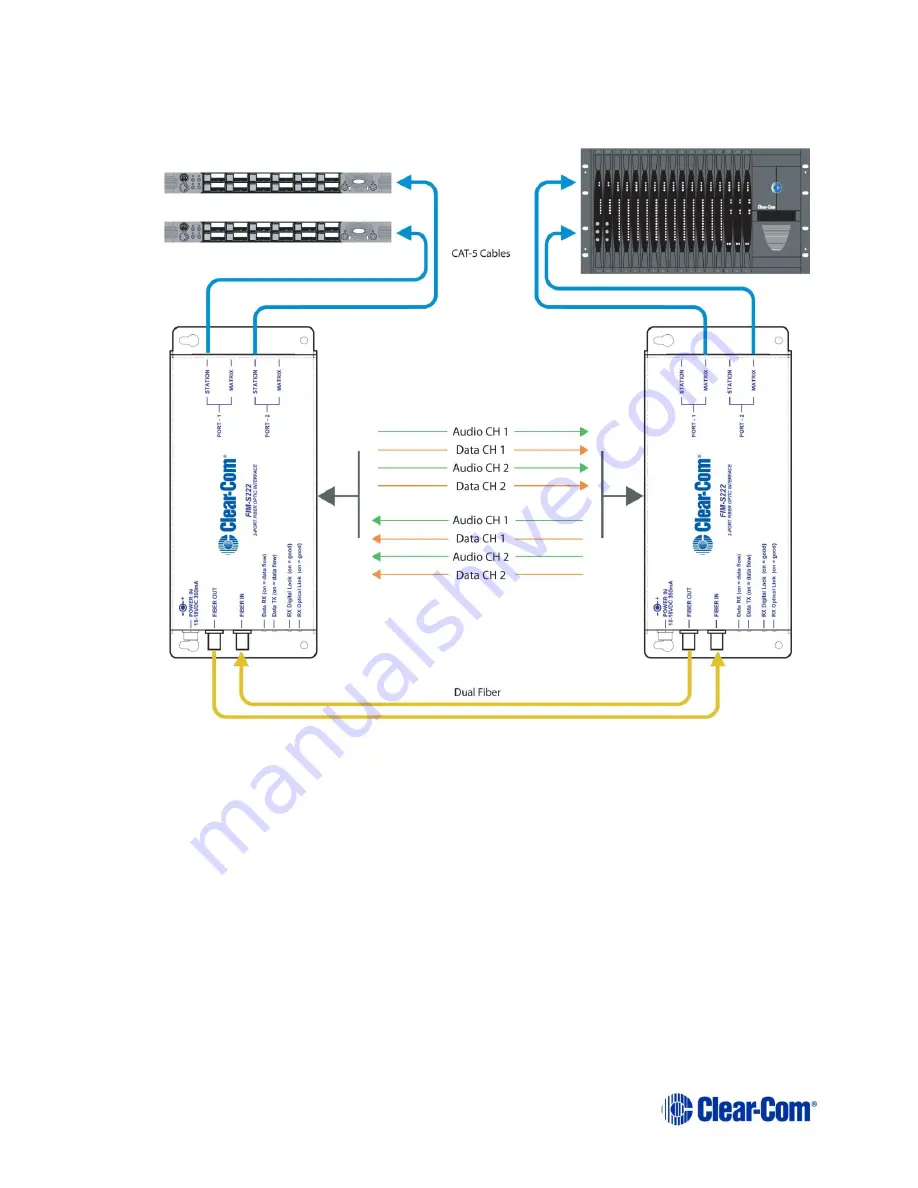
3.  The first FIM-S222 unit then multiplexes (combines) the digital audio signals with the 

already-digital data signals 


Figure 4-3 Connecting Intercom Panels to the Central Matrix 


4.  The first FIM-S222 then converts the multiplexed digital signal into an optical signal. 

5.  The first FIM-S222 then transmits the optical signal over up to 3 miles (5 km) of 

fiber-optical cable to the second FIM-S222 unit, where a similar but reverse process 
occurs to convert the signal back to its original format. 

6.  The second FIM-S222 unit converts the received optical signal to a digital signal. 

7.  The second FIM-S222 then de-multiplexes (separates) the digital signal back into 

its separate audio and data signals for each intercom unit. 

8.  The second FIM-S222 then converts the digital audio signals for each intercom 

panel to analog audio signals by sending the signals through a digital-to-analog 
converter (DAC) located on the FIM-S222 unit

’s main circuit board. 

Summary of Contents for Clear-Com FIM-S222

Page 1: ...Clear Com FIM S222 User Guide Part Number 399G132 Rev A 1 Date 6 8 15 User Guide...

Page 2: ...el Connectors and Indicators 12 4 2 FIM S222 Right Side Panel Connectors 13 4 3 Applications 13 4 3 1 Connecting Intercom Panels to the Central Matrix 13 4 3 2 Connecting Interface Modules to the Cent...

Page 3: ...eering No part of this document may be reproduced in any form by any means without prior written authorization of Clear Com an HME Company Clear Com Offices are located in California USA Cambridge UK...

Page 4: ...let Protect the power cord from being walked on or pinched particularly at plugs convenience receptacles and the point where they exit from the apparatus Only use attachments accessories specified by...

Page 5: ...ith the safety symbols in Figure 1 Safety symbols These symbols are displayed on the apparatus and warn you of the potential danger of electric shock if the system is used improperly Figure 1 1 Safety...

Page 6: ...ral matrix using fiber optic cables at distances of up to 12 miles 20 km Connecting the pair of interfaces with fiber rather than with the standard 4 wire twisted copper gives you advantages such as i...

Page 7: ...le FIM S222 units are used at each end of the fibers This unit transmits and receives at 1310 nm through the installed SFP transceiver It connects to the optical fibers through two ST connectors The u...

Page 8: ...d with isopropyl alcohol Fingerprints or other dirt on the optical connector end surfaces will reduce the received optical signal level 3 4 Connecting Fiber Optic Cable to the FIM S222 Refer to Figure...

Page 9: ...for transmission through the FIBER OUT optical connector Data arriving on the FIBER IN optical connector is demultiplexed and passed to the appropriate port for output Each port has two RJ 45 connecto...

Page 10: ...ble pinout configuration The maximum length for CAT 5 cables is 10 000 feet 3 km Figure 3 4 CAT 5 Cable Pinout Diagram 3 6 Powering the FIM S222 Power the FIM S222 by plugging the supplied external po...

Page 11: ...he unit has stabilized the left most LED will illuminate at full intensity for a moment The unit is then ready for operation 3 7 Compatibility with FIM 102D interfaces The FIM 102D and FIM S222 interf...

Page 12: ...ype socket for connection of transmit Fiber Optic Cable to other FIM S222 unit Fiber In Fiber Optic ST type socket for connection of receive Fiber Optic Cable from other FIM S222 unit RX Optical Link...

Page 13: ...audio and data signals from 1 or 2 intercom panels or interfaces to the matrix frame through the process illustrated in Figure 4 3 The text below gives a step by step description of the signal process...

Page 14: ...cal cable to the second FIM S222 unit where a similar but reverse process occurs to convert the signal back to its original format 6 The second FIM S222 unit converts the received optical signal to a...

Page 15: ...Digital to Analog D A Converters High speed digital to analog converters for each audio channel convert the digitized audio signal back to analog audio 4 3 2 Connecting Interface Modules to the Centra...

Page 16: ...FIM S222 with the EF 701M as a Stand Alone Party Line Extender Using a Clear Com EF 701M at each end of an FIM S222 set you can extend Clear Com or RTS 2 wire party line intercoms over a fiber optic...

Page 17: ...operation RX Optical Link and RX Digital Lock LEDs are lit Optical communications failure Check for broken or disconnected fibers Check to see if the FIM S222 at the other end is operating correctly...

Page 18: ...d on a rear panel that installs in the frame The card is monitored by the frame s on board controller and information about the status of the card is available through the frame s local control panel...

Page 19: ...appropriate STATION1 and STATION 2 or MATRIX 1 and MATRIX 2 The functionality of these connectors matches exactly the functionality of the connectors on the FIM S222 as described elsewhere in this man...

Page 20: ...2 output 7 RS 422 input RS 422 output 8 RS 422 input GND 9 GND GND_1 10 GND_1 6 3 Local User Interface 6 3 1 Front Card edge Interface The front card edge of the FIM 1222 incorporates two elements Sta...

Page 21: ...on the selected card flashes yellow The local control panel displays a menu that can be navigated using the four pushbuttons located beside the display The functionality of the pushbuttons is as foll...

Page 22: ...the FIM 1222 There are no adjustments or configuration options available through this menu The complete menu structure is shown in this table Menu for FIM 1222 SLOT XX Level 1 Level 2 Display Notes S...

Page 23: ...User Guide FIM S222 23 Note that the information available through the menu may also be accessed remotely if the frame is connected to a Grass Valley iControl system...

Page 24: ...80 dB Aggregate Digital Data Rate 147 456 MB Mechanical Electrical Environmental Connectors RJ 45 coaxial Optical Connectors ST type Power Connector 2 5mm Circular Input Voltage Range 9 18 Vdc Power C...

Page 25: ...TIONS While Clear Com makes every attempt to maintain the accuracy of the information contained in its product manuals the information is subject to change without notice Performance specifications in...

Page 26: ...hanges or modifications not expressly approved by Clear Com LLC an HM Electronics Inc company could void the user s authority to operate this equipment Industry Canada Compliance Statement This Class...

Page 27: ...waste equipment by handing it over to a designated collection point for the recycling of WEEE The separate collection and recycling of waste equipment at the time of disposal will help to conserve nat...

Reviews: