


43
C08UE001-1912
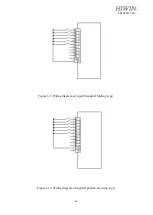
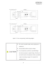
Figure 3-13 Two-wire proximity switch wiring diagram
Pin 1 and 9 are used for signal, not for input power of
end effector.
The maximum current at each pin is 100mA.
Two-wire proximity switch may cause Robot Input
error action occur due to residual voltage. Therefore, if
you want to use two-wire proximity switch, you should
connect it according to Figure 3-13 and select the
matching R value.
Two-wire proximity switch
Two-wire proximity switch
Internal circuit
Internal circuit
Positive input
Negative input
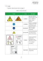
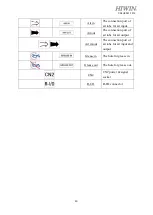
Summary of Contents for RA620-1621
Page 1: ...www hiwin tw User Manual Articulated Robot RA620 Original Instruction...
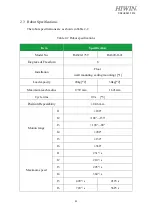
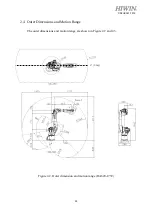
Page 35: ...34 C08UE001 1912 Figure 2 3 Outer dimension and motion range RA620 1621 J1 0 deg...
Page 37: ...36 C08UE001 1912 Figure 2 5 Wrist load diagram RA620 1621...
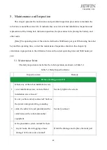
Page 54: ...53 C08UE001 1912 Table 5 3 Inspection schedule...