45
C22UE001-2004
J4-axis Zero-position setting
Step1.
Operate J4 at low speed to align the keyway of J5 with the keyway of J4.
Step2.
Insert the calibration tool (B) to the keyway to calibrate Zero-position. (hexagon
socket cap screw can be screwed first in calibration tool)
Step3.
Finish the calibration and remove the calibration tool using hexagon socket cap
screw.
Step4.
Clear encoder by HRSS.
Step5.
Zero-position setting of J4-axis is completed.
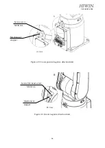
Figure 4-5(a)
Illustration of J4-axis Zero-position setting
RA605-909-GC J4-axis Zero-position setting
Step1.
Operate J4 at low speed to align the keyway of J5 with the keyway of J4.
Step2.
Insert the calibration tool (B) to the keyway to calibrate Zero-position. (hexagon
socket cap screw can be screwed first in calibration tool)
Step3.
Finish the calibration and remove the calibration tool using hexagon socket cap
screw.
Step4.
Clear encoder by HRSS.
Step5.
Zero-position setting of J4-axis is completed.
Figure 4-5(b)
Illustration of RA605-909-GC J4-axis Zero-position
Calibration tool(B)
Keyway
Hexagon socket cap screw
M3x0.5Px8L (black paint)
Calibration tool(B)
Keyway
Hexagon socket cap screw
M3x0.5Px8L (black paint)

