background image

42

43

Trainer cont.

2. Press the jog dial again to activate the menu. 

3. Rotate the jog dial to select “ACT” (activate), then press the jog 
    dial to confirm your selection and activate the trainer menu. 

6. Within the trainer menu, you can choose to limit the control 
    the student has for each channel by selecting one of the three 
    choices:
    - NOR for full control.
    - MIX for limited control.
    - OFF for no Control.

4. Scroll to highlight “MODE” and press the jog dial to activate 
    the menu.

7. To adjust the level of control for any channel, scroll to the 
    channel you want to change and press the jog dial to activate 
    the selections. 

8. Scroll to select “NOR”, “MIX”, or “OFF” and press the jog dial to 
     confirm your selection. 

Within the trainer function menu you can choose to limit the control the student has by 
selecting one of the three choices; NOR for full control, MIX for limited control or OFF for no Control. 

Within the trainer menu, you can set the FLASH 8 as a “Master radio”, set the trainer switch and activate 
the other features. To do this the transmitter must be in transmit mode. If not in the transmit mode the 
only options you will have are the “pupil options.

To configure the trainer function: 

1. From the system menu, scroll to highlight “TRAINER” and press 
    the jog dial once to enter the activation menu. 

5. Scroll to select the number of channels the student radio 
     can control:
     ALL – Gives the student access to all control channels 1~8.
     STICK – Gives the student access only to the stick (gimbal) 
     channels 1~4.
     Press the jog dial to confirm your selection

Note

Sensor

When used with the Optima series of telemetry capable receivers, the 
FLASH 8 has the ability to communicate a variety of information from 
the airplane directly to the transmitter. Refer to Section Seven Using 
the Telemetry System on page 109 for more information. 

Spectra

The spectra menu is utilized to manage the interface between the FLASH 8 transmitter and the receiver 
for each aircraft. This includes specifying the receiver type, performing a range check, binding the 
receiver, and specifying a frequency scan. All of these functions are covered in Section One: Introduction - 
Hitec 2.4GHz System. Please refer to pages 21 to 22 for complete information on the spectra menu. 
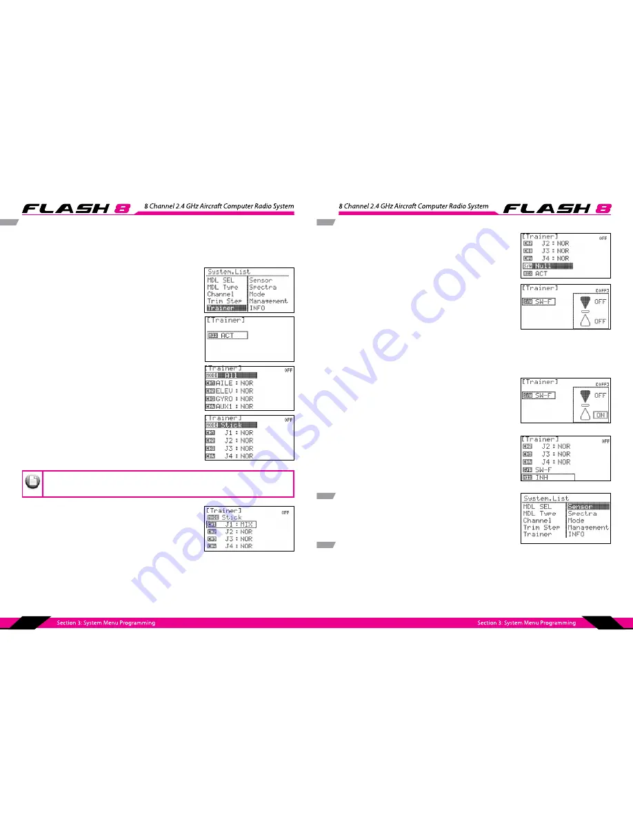
Trainer cont.

9. To select which switch will be used for the trainer function 
    scroll down to the S/W field and press the jog dial to enter the 
    switch selection menu, press the jog dial again to activate the 
    switch selections. 

10. Scroll to select a switch to activate the trainer function. Press 
       the jog dial to confirm your selection.
       - If you choose the “NULL” option, the Trainer function will 
         remain  inactive at all times for this model. 

       - If you choose a switch:


- The switch position menu will appear. Scroll to high 


   light the switch position that you will use to enable  


   the mix. Press the jog dial to confirm your selection.


- Scroll to select “ON” and press the jog dial to confirm  


   your selection. If you toggle the selected switch, the  


   field in the top right corner of the screen will indicate  


   when the mix is active.

11. Press the back button twice to return to the trainer menu.

To disable the trainer function:

1. Scroll to highlight the “MIX” field in the trainer menu and press 
    the jog dial to activate the menu.
2. Select “INH” (inhibit) and press the jog dial to confirm your 
    selection.
3. Press the back button to return to the system menu.

Summary of Contents for Flash 8

Page 1: ......

Page 2: ...8 Channel 2 4 GHz Aircraft Computer Radio System...

Page 3: ...e may not cause harmful interference 2 This device must accept any interference received including interference that may cause undesired operation This product was designed and intended for use with h...

Page 4: ...V CAMB Camber Mix GLID Only Flap Control Flap CON Landing Butterfly GLID Only Gyro Throttle Cut ACRO Only Throttle Curve ACRO Only Table of Contents 40 41 41 43 43 44 44 46 47 48 48 49 52 53 53 58 59...

Page 5: ...lished model pilots were taught by another modeler We encourage you to seek help during your early flight experiences and if required during the building and radio gear installation process Unlike som...

Page 6: ...cessary information we need to administer your repair visit our web site at www hitecrcd com to download the repair form Complete the form and send in your item for repair Hitec Service 12115 Paine St...

Page 7: ...ries 2 4GHz Receivers Model Size Weight Stock Number Minima 6 T 1 19 x 0 81 x 0 27in 30 4 x 20 8 x 7 1mm 0 22oz 6 5g 26610 Minima 6 E 1 24 x 0 81 x 0 42in 31 7 x 20 8 x 10 9mm 0 28oz 8 1g 26612 Minima...

Page 8: ...ure you use a charger suitable for the battery pack you are using It is recommended that you remove the battery from the transmitter when charging it Warning Be careful when opening the battery cover...

Page 9: ...ubber grip on the back of the radio After removing the rubber grip you may find parts in the small hall as shon on With using a small allen wrench to turn the screw you may fix the tension Clockwise t...

Page 10: ...dial Flight Condition Tip Tip 1 Function Button Used for binding the receiver to the FLASH 8 and entering the FAIL SAFE or Hold feature 2 Dual LED Status Indicator Indicates the set up process codes a...

Page 11: ...Power the Optima and Minima receivers function with up to a 35V electric aircraft motor battery 5 Telemetry Sensor and Data Port A three pin servo plug connector port is featured on the Optima 8 and O...

Page 12: ...n using a regulated Li Po or 4 8 to 6V receiver battery SERVO SERVO SERVO SERVOS ERVO Receiver Battery SERVO Engine SERVO SERVOS ERVO SERVO Receiver Battery SERVO Engine 2 4 G H z 6 C ha nn el A ir cr...

Page 13: ...d of 1 sec This means that the servos become soft and remain in their last commanded position under no load this may equate to full throttle until a valid signal is picked up again In the interests of...

Page 14: ...that confirms the signal between the receiver and transmitter is appropriate To do a range check use a power down mode to reduce the transmitter signal strength During this power down mode you should...

Page 15: ...hnology Follow these instructions to utilize SLT with your FLASH 8 Scan Mode 6 Check to see that all functions are operating correctly If they do press Finish You now have successfully bound your rece...

Page 16: ...he propeller If you are setting up a powered or un powered glider we will be programming your plane into the ACRO menu for this exercise Later you can explore the functions found in the GLID menus Not...

Page 17: ...ver is not bound linked to your transmitter you will need to follow the procedures on pages 21 22 to do so Note 5 Select the first default model NONAME 1 and press the jog dial to bring up the model m...

Page 18: ...e FLASH 8 programming structure The System function Menu and the Model function Menu The first menu we will explore will be the System Menu This menu has all the common programming function that are a...

Page 19: ...ress the jog dial to confirm your selection Model Select Menu 4 Reset the active model memory slot to factory default settings b Scroll to RESET and press the jog dial a Select the model you wish to r...

Page 20: ...powered models HELI All Helicopters will use the HELI menu Additionally there are setups for delta wing type models Elevon 2AILE 2AILE 1FLAP 2AILE 2FLAP 5 Once you have selected you wing types press t...

Page 21: ...ur selection 8 Press the back button to return to the system menu 1AILE Single aileron servo 1AILE 1FLAP Single aileron servo and single flap servo 1AILE 2FLAP Single aileron servo channel and two fla...

Page 22: ...function or transmitter control Note Trim Step The Trim Step screen is utilized to change the amount of movement seen on the servos with each adjustment or beep of the gimbal trim levers Larger values...

Page 23: ...es of telemetry capable receivers the FLASH 8 has the ability to communicate a variety of information from the airplane directly to the transmitter Refer to Section Seven Using the Telemetry System on...

Page 24: ...ghlight CONTRAST and press the jog dial to activate the menu 5 Scroll to adjust the contrast level of the display screen Press the jog dial to confirm your selection Management Menu cont 6 Scroll to h...

Page 25: ...del types are covered in Section Five and Section Six respectively Common Model Programming Menu If you have not already programmed a model with the preceding quick start guide we encourage you to do...

Page 26: ...lect high or low rates Exponential Rate EXP is a powerful function that is often used to make a twitchy model easier to control Negative exponential values typically make a model less sensitive to mod...

Page 27: ...check the sensitivity of the selected direction and then pres jog dial to confirm the changes 16 When changing only L U Left Up sensitivity use the jog dial to select L U Left Up and press to confirm...

Page 28: ...tivate the menu 6 Rotate the jog dial to increase clockwise or decrease counter clockwise the desired right AILE RUDD or down ELEV servo endpoint Press the jog dial to confirm your input 7 Press the b...

Page 29: ...lider will only be active when the switch is in the on position While this is just one example there can be many other uses so if you run into a situation where you cannot get the results you are look...

Page 30: ...select the switch that you will use to activate the mix and press the jog dial to confirm your selection If NULL is selected the mix will always be active 28 If you selected a switch the switch positi...

Page 31: ...tly enabled the condition with the highest number per the table shown above will be active The field just below the model icon on the Home screen indicates the active flight condition 5 Scroll to high...

Page 32: ...the switch position s that you will use to activate the timer Press the jog dial to confirm your selection Scroll to select ON and press the jog dial to confirm your selection If you toggle the selec...

Page 33: ...menu 7 Scroll to highlight NEU neutral and press the jog dial to confirm your selection 1 To turn the throttle lock highlight THRO Lock from the model setup menu and press the jog dial to enter the se...

Page 34: ...1 Turn on transmitter When prompted to transmit select NO 2 Verify that the active model is an ACRO or GLID model type 3 To access the model function menu press and hold the jog dial 4 The menu option...

Page 35: ...er clockwise the desired servo endpoint when a right roll command is given Press the jog dial to confirm your input Tip Tip Tip Elevon Mix cont 11 Scroll to highlight the R D right down field and pres...

Page 36: ...Ailevator feature allows the configuration of a two servo or split elevator setup It also features an aileron to split elevator mix which allows the elevators to provide roll control This feature also...

Page 37: ...he back button twice to return to the model function menu Many models especially large scale aircraft fly through turns more smoothly when aileron and rudder commands are used simultaneously The Ailer...

Page 38: ...cont Aile Rudd cont 21 Set up accordance with Flight Condition The upper right field of the menu displays which flight condition is currently active and will be programmed Scroll to the Flight Condit...

Page 39: ...o set the endpoints for the servo attached to the AIL2 receiver slot second row of the value table As with the previous settings the values input here do not affect the servo travel when roll commands...

Page 40: ...evator neutral position in each setting to maintain proper pitch trim You may also select a flight condition in this menu by activating the desired flight condition Tip Tip Tip Camber Mix GLID Only co...

Page 41: ...confirm your selection 3 Press the back button to return to the model function menu Tip Tip Tip Flap Con To configure flap control 1 From the model menu rotate the jog dial to highlight FLAP CON and...

Page 42: ...Goes with above screen shot 3 Press the back button to return to the model function menu Tip Tip Tip Landing ACRO only Landing mix controls aileron flap and elevator to perform as an air brake that r...

Page 43: ...he model menu B Fly GLID Only To configure butterfly 1 From the model menu rotate the jog dial to highlight B Fly and press the jog dial once to enter the activation menu 2 Press the jog dial again to...

Page 44: ...throttle range and the middle value is 100 B Fly Glid Only cont 20 Press the back button four times to return to the model function menu To disable butterfly 1 Scroll to highlight the MIX field in the...

Page 45: ...hrottle cut 1 From the model menu rotate the jog dial to highlight THRO CUT and press the jog dial once to enter the activation menu 2 Press the jog dial again to activate the menu 3 Rotate the jog di...

Page 46: ...modify the normally linear servo rate movement for throttle by defining five different points along the throttle response curve To configure a throttle curve T Curve Acro Only 2 Press the jog dial aga...

Page 47: ...y deadman switch Switch F is a convenient and commonly used throttle cut switch Throttle cut should be off when the switch is in its neutral position From the model function menu you can program the f...

Page 48: ...Throttle Cut is a vital safety feature when flying glow or gas powered models This feature will command the throttle servo to a preprogrammed position with a switch movement You may choose to set the...

Page 49: ...assigned a switch using the flight condition idle up function as was done on page 81 a If you choose the NULL option throttle cut will remain inactive at all times for this model b If you choose a sw...

Page 50: ...yro rate will remain active at all times for this model Gyro cont b If you choose switch The current switch position will be displayed the fore to the Rate in which is currently activated by the switc...

Page 51: ...ill be showed on the Upper right field of the menu display You may also select a flight condition in this menu by activating the desired flight condition 17 Repeat step 4 12 as applicable to define th...

Page 52: ...activate the menu 16 Rotate the jog dial to set the increase decrease of Offset for tail pitch value and press the jog dial to confirm your input Swash Thro cont 25 Scroll to select a switch to activa...

Page 53: ...erent points along the throttle response curve It is necessary to manipulate the throttle curve in conjunction with the pitch curve to achieve maximum performance from your helicopter To configure a t...

Page 54: ...hovering Press the jog button to confirm T Curve cont 20 Press the back button to return to the model function menu To disable the throttle curve 1 Scroll to highlight the MIX field in the throttle cu...

Page 55: ...el and press the jog dial to confirm the input value 14 Scroll to the S W menu field and press the jog dial to activate the menu P Curve P Curve cont You may also select a flight condition in this men...

Page 56: ...peak of its performance capability With each tweak to your model you can generate empirical data to understand the performance effects of the change All Optima receivers will report the receiver batt...

Page 57: ...using the magnetic RPM sensor If using an optical sensor select Prop 2 Prop 3 or Prop 4 The numeral indicates the number of blades on your propeller Press the jog dial to confirm your selection 1 From...

Page 58: ...ing a Y harness the display will show the total amperage for all servos connected to that output Required Sensor HTS SM Servo Manager Sensor compatible only with the HTS SS Advanced Sensor Station Not...

Page 59: ...arge dashboard type format that is highly customizable Additionally these interface modules permit logging of telemetry data for post flight playback and analysis You may also utilize the HTS Voice Te...

Reviews: