background image


1-8


StarBoard FX-77/FX-63/FX-82W 


Introduction 

English 

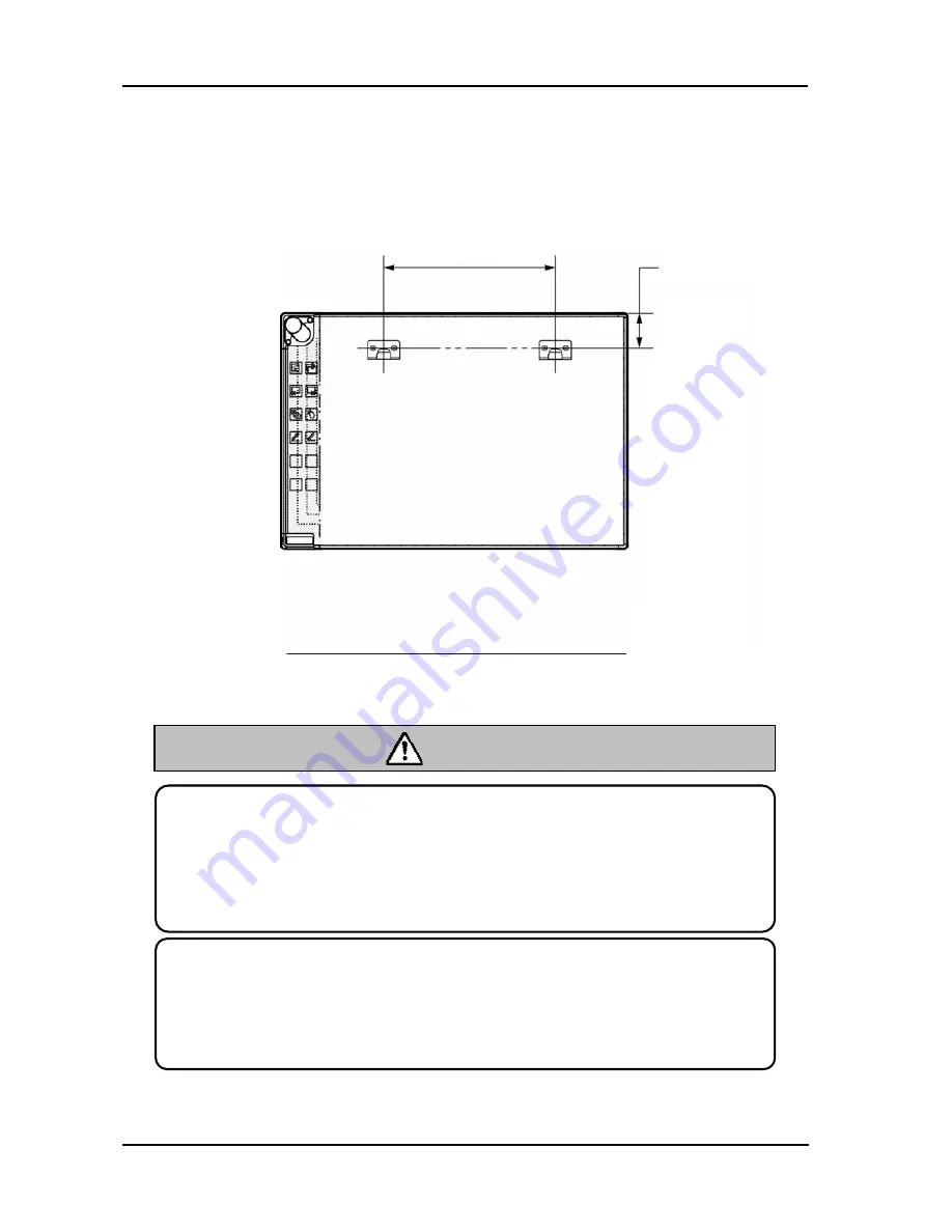
1.3.2 Wall-Mounting Setup Method   


(1) Install the mounting brackets. 

Determine the height at which the board will be installed, and install the brackets at 
the positions shown in the following diagram. 


1108±2mm/ 

43.6±0.1inch


Height


107mm/4.2inch


Before installation, take the wall material into consideration. 

If it is installed by using a method inappropriate for the wall material, the board 

might fall. 

Also, installation might be impossible, depending on the wall selected. For details, 

consult your dealer.


Before installation, take the wall strength into consideration. 

Before using the StarBoard, make sure that it has been fastened securely so that it 

will not fall. Also verify that the wall mounting bracket is strong enough to support 

a weight of approximately 88.2lb. /40 kg.


CAUTION

Height


Floor 

Summary of Contents for StarBoard FX-63

Page 1: ...sting a separate copy of this user s guide specify FXEU 051101 FXEU 051101 Read this user s guide and carefully retain it for future reference Before using this product carefully read and fully unders...

Page 2: ......

Page 3: ...t use the return and collection systems available As for details please verify the product home page Disclaimers Hitachi Software Engineering Co Ltd assumes no liability and makes no warranty either e...

Page 4: ...StarBoard FX 82W Wired AH00091 StarBoard FX 82W Wireless K W033 021 Floor Stand The StarBoard FX 77 and StarBoard FX 63 and StarBoard FX 82W incorporate eBeam technology licensed from Luidia Inc eBea...

Page 5: ...he user s guide WARNING This symbol indicates information that if ignored or applied incorrectly creates the possibility of death or serious personal injury CAUTION This symbol indicates information t...

Page 6: ...lug the powerplug Electric shock sometimes results Periodically clean the powerplug to remove dust If a dirty plug is plugged into a mains fire or electric shock might result Do not use this product n...

Page 7: ...enter unplug the power plug from the mains and contact your dealer Do not leave this product orany of its accessories on the floor Someone might step on it and break it or might be injured by trippin...

Page 8: ...s damaged f After the functionality of this product changes and repair by a service representative is considered necessary WARNINGS This product contains chemicals including lead known to the State of...

Page 9: ...hod inappropriate for the wall material the board might fall Also installation might be impossible depending on the wall selected For details consult your dealer P 1 8 Before installation take the wal...

Page 10: ...Pen 1 4 1 3 Assembly and Setup 1 5 1 3 1 Stand Setup Method 1 5 1 3 2 Wall Mounting Setup Method 1 8 1 3 3 How to Connect When Using Projection Mode 1 10 2 Usage 2 1 2 1 Basic Usage 2 1 2 1 1 Prepara...

Page 11: ...2 1 7 Wall mounting bracket 2 8 AA alkaline Battery 2 9 StarBoard Software x x CD ROM 3 2 10 User s Guide this manual 1 11 StarBoard Software x x User s guide 3 1 12 Warranty Sheet 1 1 3 4 5 is bundl...

Page 12: ...hand version 1 5 Board receiving bracket right hand version 1 6 Board fixing bracket 2 7 Hex socket head cap screw with collar 8 8 Hex socket head cap screw 4 9 Panhead screw 8 10 Triangular knob scre...

Page 13: ...nctions used frequently in applications are located here Please refer to the next page for details 3 Pen Input Active Area Annotations and graphics drawn in this area are stored into the PC When using...

Page 14: ...as desired Please refer to the online help for details Symbol Description Symbol Description Show Hide the StarBoard Software toolbar Insert and show a blank page Show previous page Show next page Sh...

Page 15: ...ow temperature or humidity or that are exposed to direct sunlight 1 3 1 Stand Setup Method Reconfirm that all parts are present before assembling and setting up the stand 1 Stand Assembly Assemble the...

Page 16: ...board will be installed and use the square holes on the back of the board to hang it on the board receiving brackets b Verify that one of the board s square holes is attached securely to the board rec...

Page 17: ...riangular knob screw at the bottom of each side b Raise the board and re hang it by attaching the square holes for the desired height to the receiving brackets c Fasten the triangular knob screw at th...

Page 18: ...e wall material into consideration If it is installed by using a method inappropriate for the wall material the board might fall Also installation might be impossible depending on the wall selected Fo...

Page 19: ...age CAUTION NOTE The equipment might malfunction if set up in an excessively bright location If the ceiling lights are too bright it will be necessary to adjust the brightness by turning off the light...

Page 20: ...dure 1 Connect the RGB cable to the projector s RGB terminal and fasten with the integral screws 2 Connect the opposite side of the RGB cable connected in step 1 to the PC s RGB terminal and fasten wi...

Page 21: ...step 1 to the PC s RGB terminal and fasten with the integral screws 3 Connect the Bluetooth adaptor option to the PC s USB terminal 4 Connect the power supplies of the PC and the projector to the main...

Page 22: ......

Page 23: ...the side faces to the pen tip 3 Replace the battery cover and slide it in the direction of the arrow until it closes completely Be sure to orient the battery correctly Do not reverse the and terminals...

Page 24: ...he electronic pen sometimes is not transmitted correctly If the annotations and graphics drawn on the whiteboard are not stored correctly to the PC change your grip on the electronic pen and then veri...

Page 25: ...he same spot Drag Push the pen tip onto the starboard with sufficient force and without releasing it away from the broad move it from one point to another 2 1 4 Electronic Pen Setting The electronic p...

Page 26: ...he PC are properly connected to each other You can perform the board detection using the StarBoard Software Refer to the StarBoard Software User s Guide for details 6 Refer to the StarBoard Software U...

Page 27: ...ower up the projector 3 Power up PC to start up Windows 4 Adjust the position of the projector so that the Windows screen projected by the projector is within the pen input active area see page 1 3 Fo...

Page 28: ......

Page 29: ...ing stand mm 1 793 W 1 700 2 050 H 620 D 1 500 W 1 700 2 050 H 620 D IR wavelength 880 nm Ultrasonic frequency 40 KHz Sampling rate Approximately 66 points s Accuracy 1 5 mm Current input voltage 200m...

Page 30: ...20 D IR wavelength 880 nm Ultrasonic frequency 40 KHz Sampling rate Approximately 66 points s Accuracy 1 5 mm Current input voltage 200mA 5V AC adapter input voltage power consumption 100 240 V 0 5 W...

Page 31: ...rranty excluding wear and physical damage Not covered by warranty 3 Please refer to the warranty sheet for this product s warranty service period 4 Even during the warranty period there will be a repa...

Page 32: ...e product must be repaired so please contact them If the customer sends the product to our company without RMA Return Merchandise Authorisation number it might not be covered by warranty 6 As a rule t...

Reviews: