background image

--- 17 ---

14

12

10

8

6

Batter

y v

olta

g

e

4

2

0

Tightening tor

que

M16 x 55 (5/8" x 2-5/32") F10T (tightening time: 3 seconds)

Number of bolts driven per charge (EB 14B battery)

20

40

60

80

100

120

(pcs.)

0

40

80

120

160

Fully discharged

Battery voltage

Fully charged

α

400

800

1200

1600

(kgf•cm) (N•m)

(1389 in-lbs.)

(1042 in-lbs.)

(694 in-lbs.)

(347 in-lbs.)

0

400

800

1200

(in-lbs.)

(V)

Tightening torque

7-2. Tightening Torque Inspection Prior to Operation

As described and shown in Para. 6-2-3, the output tightening torque of which the Model WR 14DH is capable in

excess of the rated tightening torque of certain bolts and screws.  Accordingly, if the tightening time is prolonged

for such bolts and screws, it could cause damage to their threads or, in the worst case, cause them to be sheared

off.  (This phenomenon is common to all existing impact wrenches).  Particularly when tightening M6 (1/4") or

smaller screws, tightening time must be kept extremely short: 0.5 seconds or less.  The customer should be

advised to carry out several bolt tightening operations and adjust the tightening time as necessary by measuring

the tightening torque with an appropriate torque wrench before commencing continuous operation.

7-3. Tightening Torque Variation

The tightening torque of the cordless impact wrench may vary slightly in accordance with the factors described

below.  Sales persons are requested to advise the customer to confirm that appropriate tightening torque is

obtained by measuring the torque with an appropriate torque wrench or torque driver at the beginning of the

tightening operations, and as necessary during the tightening operations.  In addition, the torque values shown in

Para. 6-2-2 above are useful as a handy reference, and may be utilized as tentative standards.

(1) Voltage of battery

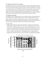
Tightening torque is affected by the voltage output of the battery.  For example, the relationship between

tightening torque and the number of M16 x 55 mm (5/8" x 2-5/32") bolts tightened is shown in Fig. 7 below.

As can be seen in the graph, tightening torque decreases as the number of bolts tightened increases. This

phenomenon is caused by the decline in voltage output of the battery due to the increasing number of bolts

tightened.  In particular, the tightening torque decreases rapidly just before the battery is fully discharged

(range "a" in the graph).  As this phenomenon is an inherent drawback in any cordless impact wrench,

salespersons are requested to ensure that the customer is fully aware of and understands this characteristic.

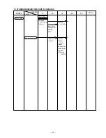
Fig. 7

Summary of Contents for WR 14DH

Page 1: ...POWER TOOLS TECHNICAL DATA AND SERVICE MANUAL CORDLESS IMPACT WRENCH WR 14DH SPECIFICATIONS AND PARTS ARE SUBJECT TO CHANGE FOR IMPROVEMENT LIST No F841 Aug 2000 W MODEL WR 14DH ...

Page 2: ...f Bolts Driven 14 7 PRECAUTIONS IN SALES PROMOTION 15 7 1 Safety Instructions 15 7 2 Tightening Torque Inspection Prior to Operation 17 7 3 Tightening Torque Variation 17 7 4 Suggestions and Precautions for the Efficient Use of the Charger 18 8 OTHER PRECAUTIONS 19 9 REPAIR GUIDE 20 9 1 Precautions in Disassembly and Reassembly 20 9 2 Precautions in Disassembly and Reassembly of Battery Charger 26...

Page 3: ...nd grip rubber The Model WR 14DH broadens our lineup of cordless impact wreches from 9 6 V to 14 4 V Vigorous sales promotion of the impact wrench series is anticipated in various applications such as construction electric equipment sanitary facilities and motor vehicles 3 APPLICATIONS Construction industry Assembly of scaffolding roofing fencing etc removal of plastic cones from concrete forms mo...

Page 4: ... tightening torque Convenient holes for hanging Externally accessible carbon brushes for longer motor life Well balanced handle for less fatigue Comfort grip rubber Variable speed switch with electric brake for efficient operation Compact and lightweight 2 2 kg 4 85 lb 223 mm 8 25 32 2 7 m m 1 1 6 ...

Page 5: ...19 4 mm 3 4 C Position of center of gravity 27 mm 1 1 16 A Center height D A n g le o f h a n d le Work center line Center of gravity 10 HITACHI WR 14DH Weight Catalog weight kg C L Overall length mm Hitachi Maker Model A Center height mm B Switch position mm C Position of center of gravity mm D Angle of handle Actual weight kg WR 14DH 223 8 25 32 27 1 1 16 47 2 1 53 64 19 4 3 4 10 WH 12D 230 9 3 ...

Page 6: ...the connecting portion on the outside of the brush tube 4 Safe handle shape Compared with the previous WH 12D the housing of the Model WR 14DH does not produce gaps caused by vibration because front and rear grip inserts part name grip R and grip F made of rubber are provided at the juncture of the handle and the housing is secured with two screws at the center of the handle to prevent the operato...

Page 7: ...ely 1 000 cycles in case of Model UC 14YF2 Nominal capacity 2 0 Ah Sealed cylindrical nickel cadmium batteries Nominal voltage DC 14 4 V Nominal life Charging discharging approximately 500 cycles in case of Model UC 14YF2 Nominal capacity 3 0 Ah Sealed power source Single phase AC 50 60 Hz Voltage Depending on the order specification Power input 44 W Charging system constant current charge with fu...

Page 8: ...FF Storage battery or charger is faulty Charging not possible because storage battery temperature is too high Pilot to lamp indications UC 14YF2 5 2 Optional Accessories 1 Combination of optional accessories and applications Square drive dimension 12 7 m 1 2 square Tools Applicable screws Connecting tools Hex socket hd bolt and nut Hex socket hd bolt Socket for ducting Hex socket Square drive dime...

Page 9: ... 16 38 1 1 2 M 8 5 16 M 10 3 8 M 10 3 8 M 12 15 32 W 3 8 M 12 15 32 M 14 9 16 M 12 15 32 M 14 9 16 M 16 5 8 M 16 5 8 M 18 23 32 Part Name Hexagon socket 10 mm 22 mm 21 mm 19 mm 17 mm 14 mm 13 mm 12 mm 24 mm Code No 873632 873626 873624 873536 873539 873540 944291 873627 873629 Shape B B B D D C C B D Dihedral width H mm 10 3 8 12 15 32 19 23 32 17 21 32 14 9 16 13 1 2 22 7 8 21 53 64 24 15 16 M 8 ...

Page 10: ...32 34 1 11 32 20 25 32 52 2 3 64 20 25 32 34 1 11 32 21 5 53 64 52 2 3 64 20 25 32 34 1 11 32 22 7 8 52 2 3 64 24 15 16 34 1 11 32 25 1 75 2 15 16 24 15 16 57 2 1 4 25 1 52 2 3 64 24 15 16 34 1 11 32 28 1 3 32 52 2 3 64 24 15 16 24 15 16 28 1 3 32 75 2 15 16 24 15 16 57 2 1 4 31 1 7 32 W 1 2 125 4 47 51 24 15 16 107 4 7 32 31 1 7 32 34 1 11 32 34 1 11 32 34 1 11 32 52 2 3 64 52 2 3 64 24 15 16 32 ...

Page 11: ...ld the unit during its operation Carefuly read the warnings attached to the holster for safe use Hook Code No 308090 Use the holster to hold the unit during its operation Carefuly read the instructions that come with the hook to learn how to use it ...

Page 12: ...7 mm 1 2 square drive Plunger type 12 7 mm 1 2 square drive Plunger type Type of switch Nominal capacity Nominal voltage Ambient temperature Type Battery Power input capacity Recharging voltage Model Charger N m min 1 min 1 kg N m min 1 min 1 mm mm kg dB A V A V C Ah VA V Plastic tool case Charger UC 14YF2 Plastic tool case Charger UC 12Y Plastic tool case Charger UC 14YF2 Plastic tool case Charge...

Page 13: ...gh power motor and the higher moment of inertia of the hammer The tightening torque does not drop even when loosening bolts because the motor runs at the same torque and speed in both the forward and reverse directions Tightening torque comparisons of Model WR 14DH with previous models are shown in Fig 4 It should be noted that M16 5 8 bolt F10T were utilized in the tests to ensure that the bolts ...

Page 14: ...he thread mm2 Strength grade and rated axial stress of threads Table 1 Strength grade Material Rated axial stress kgf mm2 Heat treatment 4 8 6 8 8 8 12 9 29 1 43 7 58 2 95 Mild steel Alloy steel including Ni Mn Cr etc None Processed hard material Diameter and effective sectional areas of threads Table 2 Thread diameter and appropriate tightening torque Fig 5 Effective sectinal area of thread mm2 K...

Page 15: ...point or durable force 45 500 psi Tensile strength of the bolt 56 900 psi Nut Steel plate thickness t 0 1 2 3 sec M10 x 30 3 8 x 1 5 32 Tightening time Steel plate thickness t 10 mm 3 8 High strength bolt Ordinary bolt 0 20 40 60 80 100 120 140 160 0 200 400 600 800 1000 1200 1400 1600 174 in lbs 347 in lbs 521 in lbs 694 in lbs 868 in lbs 1042 in lbs 1215 in lbs 1389 in lbs kgf cm N m 200 400 600...

Page 16: ...can be tightened per charge will vary slightly depending on bolts tightening conditions bolt sizes ambient temperatures and the charging capacity of the battery Ordinary bolt Cordless impact wrench Battery M10 3 8 ordinary bolt Tightening condition EB 14B M12 15 32 ordinary bolt M14 9 16 ordinary bolt Number of bolts Time sec HITACHI WR 14DH Number of bolts Time sec Number of bolts Time sec Model ...

Page 17: ...ted on the unit If this order is reversed the charger may not function properly 4 Ensure the power source voltage is the same as that indicated on the Name Plate of the charger Use of any other power source DC outlet fuel powered generator etc will cause the charger to overheat and burn out 5 Do not use any voltage increasing equipment transformer etc between the power source and the charger If th...

Page 18: ...ry 10 Disposal of the Type EB 14B or EB 1430H Storage Battery Ensure that all customers understand that Type EB 14B or EB 1430H Storage Batteries should be turned into any Hitachi power tool sales outlet or authorized service center when they are no longer capable of being recharged or repaired If thrown into a fire the batteries may explode or if discarded indiscriminately leakage of the cadmium ...

Page 19: ...ing continuous operation 7 3 Tightening Torque Variation The tightening torque of the cordless impact wrench may vary slightly in accordance with the factors described below Sales persons are requested to advise the customer to confirm that appropriate tightening torque is obtained by measuring the torque with an appropriate torque wrench or torque driver at the beginning of the tightening operati...

Page 20: ...he socket which is fitted onto the anvil in the main body will become worn and loose Wear and looseness will cause a proportionate loss of tightening torque In addition use of an incorrect size socket slightly larger than the bolt being tightened will also result in decreased torque 7 Bolt and nut rotate together Tightening torque that can be achieved will be considerably decreased if the bolt and...

Page 21: ...torque but could also easily cause damage to the socket Please refer to the tables in para 5 2 for appropriate socket dimensions 3 Hammering section lubrication Grease ATTOLUB MS No 2 is utilized in the hammering section Frequent or continuous use of the tool will cause excessive temperature rise of the hammering section resulting in depletion of the grease and subsequent increased wear of compone...

Page 22: ... Screws D4 x 20 26 from the main body to remove Housing B 3 Remove the DC Speed Control Switch 31 Fin Ass y 33 Motor 22 Grip F 34 and Grip R 35 together Remove the Pushing Button 32 and the Strap 36 4 Disassembly of the switch ass y Remove the two Machine Screws M3 x 5 30 that secure the flag terminal and then disconnect the internal wires purple and black of the Motor 22 from the DC Speed Control...

Page 23: ...osition extract the two Steel Balls D5 556 6 from the cam grooves of the Spindle 13 and the Hammer 7 with a small flat blade screwdriver or a similar tool Then slowly release the hand press and lift the Hammer 7 and Washer S 11 together to extract them from the Spindle 13 Spring A 10 can then be removed Top of spindle cam Steel Ball D5 556 6 Spindle 13 Hammer 7 Raised faces of hammer Steel ball gu...

Page 24: ...Make sure that the internal wire purple is passed under the motor so that it is not caught between the motor and housing A d Mount the DC Speed Control Switch 31 to Housing A so that the projection of the forwarding reversing lever at the top of the Switch is inserted into the U shaped groove of the Pushing Button 32 Secure the Fin Ass y 33 to the FET of the DC Speed Control Switch 31 with the S T...

Page 25: ...0 SW lead wire Terminal support DC speed control switch S tight screw D3 5 x 6 Purple Pinion Black FET Fin Motor Lead wire Purple Projection of forward reverse lever Machine screw M3 x 5 Terminal Lead wire Black ...

Page 26: ...Damper 25 Application of silicone rubber to the Inner Cover 19 Rear Damper 25 Internal wire purple Greasing position of the Inner Cover 19 Groove for purple internal wire Fold the lead wire Internal wire black Groove for black internal wire ...

Page 27: ...nvil C Ass y 4 then the Hammer Case 2 4 Mounting the assembly from the Hammer Case 2 to the Inner Cover 19 to the housing assembly Push the assembly from the Hammer Case 2 to the Inner Cover 19 into the housing assembly by turning them clockwise and counterclockwise Check that the anvil can be easily turned If it cannot be turned check for correct mesh of the gears Secure the above assembly with t...

Page 28: ...tions in Disassembly and Reassembly of Battery Charger Refer to the Technical Data and Service Manual for precautions in disassembly and reassembly of the Model UC 14YF2 battery charger 1 96 0 49 N m 20 5 kgf cm 17 4 4 3 in lbs 1 96 0 49 N m 20 5 kgf cm 17 4 4 3 in lbs 1 47 1 96 N m 15 20 kgf cm 13 17 4 in lbs 0 29 0 39 N m 3 4 kgf cm 2 6 3 5 in lbs ...

Page 29: ...0 Fixed Variable WR 14DH Work Flow Inner Cover O ring S 20 Damper Motor 60 min 50 Hammer Case Anvil B DC speed Control Switch Fin Ass y Housing A B Set Steel Ball Hammer Spring A Spindle Idle Gear Set Needle Roller Ring Gear Ball Bearing 6001VV General Assembly ...

Page 30: ... 28 CORDLESS IMPACT WRENCH Model WR 14DH 2000 6 20 E1 LIST NO F841 ELECTRIC TOOL PARTS LIST ...

Page 31: ...RING GEAR 1 17 991 455 WASHER C 1 18 600 1VV BALL BEARING 6001VVCMPS2L 1 19 318 373 INNER COVER 1 20 876 078 O RING S 20 1 21 306 302 DAMPER 1 22 318 381 MOTOR 1 23 999 058 CARBON BRUSH 1 PAIR 2 24 318 390 BRUSH CAP 2 25 318 380 REAR DAMPER 1 26 302 086 TAPPING SCREW W FLANGE D4X20 BLACK 7 27 NAME PLATE 1 28 HITACHI LABEL 1 29 319 252 HOUSING A B SET 1 INCLUD 34 35 30 994 532 MACHINE SCREW W SP WA...

Page 32: ...NT PIN 1 625 991 476 BIT ADAPTER ASS Y 1 INCLUD 621 622 626 991 480 HEX SOCKET ASS Y LONG 21MMX125L 1 INCLUD 621 622 627 944 291 HEX SOCKET ASS Y 10MMX40L 1 INCLUD 621 622 628 873 632 HEX SOCKET ASS Y 12MMX40L 1 INCLUD 621 622 629 873 539 HEX SOCKET ASS Y 13MMX40L 1 INCLUD 621 622 630 873 540 HEX SOCKET ASS Y 14MMX40L 1 INCLUD 621 622 631 873 536 HEX SOCKET ASS Y 17MMX32L 1 INCLUD 621 622 632 873 ...

Page 33: ...CLUD 621 622 646 955 143 HEX SOCKET ASS Y LONG 21MMX52L 1 INCLUD 621 622 647 955 144 HEX SOCKET ASS Y LONG 22MMX52L 1 INCLUD 621 622 648 992 613 SOCKET ASS Y FOR DUCT 13MMX95L 1 INCLUD 621 622 649 649 992 614 SOCKET FOR DUCT 13MMX52L 1 650 992 615 SOCKET ASS Y FOR DUCT 14MMX95L 1 INCLUD 621 622 651 651 992 616 SOCKET FOR DUCT 14MMX52L 1 652 993 658 SOCKET ASS Y FOR DUCT 12MMX95L 1 INCLUD 621 622 6...

Reviews: