background image

--- 25 ---

(2) Removal of Front Cap (A) 

[5] <1>

 and Protector (B) 

[6]

 (A) 

<2>

Insert a small flat-blade screwdriver between Front Cap (A) 

[5] <1>

 and Protector (B) 

[6]

 (A) 

<2>

 and remove

them from the Hammer Case 

[8] <4>

.

(3) Removal of the Hammer Case 

[8] <4>

 and the hammer assembly

Remove the four Tapping Screws (W/Sp. Washer) D4 x 25 (Black) 

[7] <3>

 that connect the Hammer Case 

[8]

<4>

 to Housing (A). (B) Set 

[34] <30>

 and remove the Hammer Case 

[8] <4>

 and the hammer assembly from

Housing (A). (B) Set 

[34] <30>

.

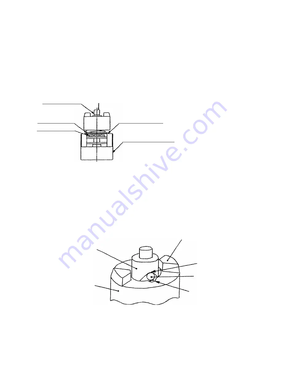
(4) Disassembly of the hammer assembly

Washer (S) 

[15] <11>

Push down.

Spindle 

[17] <13>

Hammer Spring

[14] <10>

Stopper 

[16] <12>

J-297 base for washer (S)

Fig. 2

Mount the hammer assembly onto the

J-297 base for washer (S).  With a

hand press, push down the top of the

Spindle 

[17] <13>

 to compress the

Hammer Spring 

[14] <10>

.  In this

position, remove the Stopper 

[16]

<12>

 with a small flat-blade

screwdriver, then release the hand

press. (See Fig. 2).

Remove the hammer assembly from the J-297 base for washer (S) and support the end surface of the Spindle

[17] <13>

.  With a hand press, push down either of the raised faces of the Hammer 

[12] <7>

 to compress

Hammer Spring 

[14] <10>

.  In this position, extract the two Steel Balls D 5.556 

[11] <6>

 from the cam grooves

of the Spindle 

[17] <13>

 and the Hammer 

[12] <7>

 with a small flat-blade screwdriver and remove them from

the steel ball guide groove.  Then, slowly release the hand press and lift the Hammer 

[12] <7>

 and Washer (S)

[15] <11>

 together to extract them from the Spindle 

[17] <13>

.  Hammer Spring 

[14] <10>

 can then be

removed.

Steel ball guide groove

Spindle 

[17] <13>

Hammer 

[12] <7>

Raised faces of hammer

Top of spindle cam

Steel Ball D5.556 

[11] <6>

Fig. 3

(5) Removal of the Hook Ass'y 

[41] <37>

Remove the Special Screw M5 

[48] <44>

 with a flat-blade screwdriver or a coin and remove the Hook Ass'y

[41] <37>

 and the Hook Spring 

[47] <43>

.

Summary of Contents for WH 9DM2

Page 1: ...AL CORDLESS IMPACT DRIVER WH 9DM2 CORDLESS IMPACT WRENCH WR 9DM2 SPECIFICATIONS AND PARTS ARE SUBJECT TO CHANGE FOR IMPROVEMENT LIST Nos WH 9DM2 G801 WR 9DM2 G802 Mar 2004 G MODELS WH 9DM2 WH 9DM2 WR 9DM2 WR 9DM2 Hitachi Power Tools ...

Page 2: ... are used in the place of company name s and model name s of our competitor s The symbol s utilized here is are as follows Symbol Utilized Competitor Company Name Model Name C MAKITA BTD061 WH 9DM2 Symbol Utilized Competitor Company Name Model Name C MAKITA 6991D WR 9DM2 ...

Page 3: ... Torque 14 6 4 Tightening Speed 17 6 5 Number of Screws or Bolts Driven 18 7 PRECAUTIONS IN SALES PROMOTION 19 7 1 Safety Instructions 19 7 2 Tightening Torque Inspection Prior to Operation 21 7 3 Tightening Torque Variation 21 7 4 Suggestions and Precautions for the Efficient Use of the Charger 22 8 OTHER PRECAUTIONS 23 9 REPAIR GUIDE 24 9 1 Precautions in Disassembly and Reassembly 24 9 2 Precau...

Page 4: ...40 higher than the current Model WR 9DM 3 APPLICATIONS Tightening loosening of small screws tapping screws wood screws bolts nuts etc Drilling into wood and various other materials with use of optional accessory drill chuck adapter Applicable Markets Wood product assembly Tightening loosening of wood screws lag bolts etc Construction industry Assembly of scaffolding roofing aluminum sashes fencing...

Page 5: ... long service life Advanced case excellent accommodation 4 SELLING POINTS 1 Cordless impact driver Model WH 9DM2 The shortest overall length in the class 147 mm Convenient for work in narrow places Lightweight 1 2 kg Easy to operate for a long time Easily portable 30 lower striking start torque Optimum for light duty works such as tightening sash screws plastic screws and Teks screws ...

Page 6: ...the Model WR 12DM2 New design Elastomer is new titanium silver color Protector is standard Convenient light equipped hook High durability dust resistance and long service life Advanced case excellent accommodation Class top tightening torque 120 N m 1220 kgf cm C 100 N m Compact Overall length 160 mm C 168 mm ...

Page 7: ...Equipped with a new rare earth magnet motor having 1 2 times greater magnetic force Same as the Model WH 12DM2 The Model WH 9DM2 is equipped with a new rare earth magnet motor that is smaller than the Model WH 9DM by 30 while providing higher power Equipped with a reinforced plastic gear for the decelerating unit The gear is made of heat resistant nylon resin reinforced with fiberglass It is light...

Page 8: ...inimize damage to the screws Thanks to the lower striking start torque the Model WH 9DM2 is optimum for light duty works such as tightening sash screws plastic screws and Teks screws because it gives less damage to the small screws and the workpieces Table 1 shows a comparison of number of trigger switch operations when tightening a tapping screw D4 x 25 in a workpiece of nylon resin prepared hole...

Page 9: ...nit mm Center height mm Height mm Overall length Measured value kg kg Catalog value Weight Hitachi WR 9DM2 160 6 19 64 26 5 1 3 64 223 8 25 32 1 4 3 lbs 1 43 3 1 lbs Hitachi WR 9DM 167 6 37 64 26 1 1 64 221 8 45 64 1 4 3 lbs 1 46 3 2 lbs 168 6 39 64 26 1 1 64 231 9 3 32 1 4 3 lbs 1 49 3 3 lbs C 122 88 93 160 140 120 100 80 60 40 20 0 WR 9DM2 WR 9DM C Tightening torque N m 2 Compact The overall len...

Page 10: ...kel cadmium batteries Nominal voltage DC 9 6V Nominal life Charging discharging approximately 1 000 cycles in the case of Model UC 14YF2 UC 14YFA Nominal capacity 2 0 Ah 160 mm 6 37 64 x 223 mm 8 25 32 Battery Type EB 930H Sealed cylindrical nickel metal hydride batteries Nominal voltage DC 9 6V Nominal life Charging discharging approximately 500 cycles in the case of Model UC 14YF2 UC 14YFA Nomin...

Page 11: ... 930H type battery is 45 C 1 In the case of tapping screws and wood screws a minimum of M3 1 8 is possible 2 This torque is based on tightening an M12 15 32 bolt strength grade 12 9 for 3 seconds with a hexagonal socket 3 This torque is based on tightening an M12 15 32 bolt strength grade 12 9 for 3 seconds with a hexagonal socket 4 Main body does not include accessory tools and hook hexagonal bit...

Page 12: ... 2 9 16 12 5 16 Hexagon socket 996179 13 1 2 65 2 9 16 13 8 mm Hexagon socket 996180 14 9 16 65 2 9 16 14 10 mm Hexagon socket small type 996181 16 5 8 65 2 9 16 16 10 mm Hexagon socket 996182 17 21 32 65 2 9 16 17 10 mm Hexagon socket 996197 21 53 64 166 6 17 32 21 1 2 Hexagon long socket Woodworking drill bit Code No 959183 14 mm dia 35 64 83 mm 3 17 64 Drill chuck adaptor set Code No 996195 The...

Page 13: ...mensions and applicable bolts for accessory long sockets Shape B Shape D 8 mm 10 mm 12 mm 13 mm 14 mm 16 mm 17 mm 18 mm 19 mm 48 1 7 8 48 1 7 8 48 1 7 8 48 1 7 8 48 1 7 8 48 1 7 8 48 1 7 8 48 1 7 8 48 1 7 8 60 2 3 8 60 2 3 8 60 2 3 8 60 2 3 8 60 2 3 8 60 2 3 8 60 2 3 8 60 2 3 8 60 2 3 8 B B B B B D D D D 8 5 16 10 3 8 12 15 32 13 1 2 14 9 16 16 5 8 17 21 32 18 23 32 19 3 4 W 5 16 W 3 8 W 7 16 M 5 ...

Page 14: ...Universal joint Code No 996147 12 7 mm 1 2 square adapter ass y Overall length 36 mm 1 13 32 Code No 996145 Square drive dimensions Anvil side 9 5 mm 3 8 Socket side 12 7 mm 1 2 Part name Overall length Code No Cross recessed Phillips hd driver bit No 2 45 955229 70 955654 45 955230 70 955655 Cross recessed Phillips hd driver bit No 3 ...

Page 15: ...3 2 5 lbs Main body weight kg 70 69 70 No load sound pressure level dB A Driver chuck Driver chuck Driver chuck Tool tip mounting system Trigger switch with forward reverse changeover pushing button with brake and variable Type of switch Trigger switch with forward reverse changeover pushing button with brake and variable Trigger switch with forward reverse changeover pushing button with brake and...

Page 16: ...e V Plastic tool case Charger UC 14YF2 or UC 14YFA Standard accessories Charger 1 Max tightening torque is based on tightening an M12 5 32 bolt strength grade 12 9 for 3 seconds with a hexagon socket 2 Main body weight does not include accessory tools hexagon bit etc 1 2 1 2 WR 9DM M 6 M 14 1 4 9 16 M 6 M 10 1 4 3 8 120 1220 kgf cm 1060 in lbs 0 2 300 0 3 000 1 4 3 0 lbs 88 2 900 kgf cm 780 in lbs...

Page 17: ...ssory tool Hexagon socket ass y 2 Impact wrench Test conditions Bolt M12 x 45 mm 15 32 x 1 3 4 strength grade 12 9 Steel plate Mild steel M12 15 32 Thickness 25 mm 1 Accessory tool Hexagon socket ass y WH 9DM WH 9DM2 200 174 in lbs 0 1 2 3 400 347 in lbs 600 521 in lbs 800 694 in lbs 1000 868 in lbs kgf cm Tightening time Tightening torque C 1200 1042 in lbs N m 120 100 80 20 40 60 0 0 sec WR 9DM2...

Page 18: ...he thread mm2 Strength grade and rated axial stress of threads Strength grade Rated axial stress kgf mm2 Material Heat treatment 4 8 6 8 8 8 12 9 29 1 43 7 58 2 95 Mild steel Alloy steel including Ni Mn Cr etc None Processed hard material Diameter and effective sectional areas of threads Kind of thread x pitch Effective sectional area of thread mm2 M5 x 0 8 mm 3 16 14 2 M6 x 1 mm 1 4 20 1 M8 x 1 2...

Page 19: ...ess t 3 8 10 mm 5 16 x 1 3 6 M8 x 30 Tightening torque High strength bolt 0 0 20 40 60 80 100 N m 0 1 2 3 kgf cm in lbs 3 8 x 1 3 16 M10 x 30 Tightening torque High strength bolt 0 0 20 40 60 80 100 N m Ordinary bolt 0 1 2 3 15 32 x 1 3 4 M12 x 45 High strength bolt Ordinary bolt kgf cm in lbs Tightening torque 0 0 20 40 60 80 100 N m 1200 1042 120 200 174 400 347 600 521 800 694 1000 868 Tighteni...

Page 20: ...mm dia 120 mm length lauan 2 Wood screw 4 2 mm dia 75 mm length lauan 1 Wood screw 4 0 mm dia 50 mm length lauan HITACHI WH 9DM2 HITACHI WH 9DM C 1 5 sec Model sec 1 3 sec 2 0 sec 1 2 3 4 5 Fast Slow 2 7 sec Model sec 2 3 sec 3 5 sec 1 2 3 4 5 Fast Slow 4 6 sec Model sec 4 0 sec 6 3 sec Fast Slow 10 0 sec Model 9 2 sec 15 0 sec 1 2 3 4 5 6 7 8 9 10 sec Fast Slow 2 4 6 8 10 12 14 16 18 20 HITACHI W...

Page 21: ...Ah Wood screw 4 0 mm dia and 50 mm length Workpiece Cedar no prepared hole 350 390 295 1 130 1 030 1 410 Machine screw M8 x 16L 2 Ordinary bolts Cordless impact wrench Model WR 9DM2 Comparison data on the number of bolts which can be tightened per battery charge are shown in the table below Please note that the data below are intended for general reference only as the number of bolts which can be ...

Page 22: ...oltage matches that indicated on the unit If this order is reversed the charger may not function properly 4 Ensure the power source voltage is the same as that indicated on the Name Plate of the charger Use of any other power source DC outlet fuel powered generator etc will cause the charger to overheat and burn out 5 Do not use any voltage increasing equipment transformer etc between the power so...

Page 23: ...rvice center in the event repair or replacement is necessary 10 Disposal of the Type EB 9B or EB 930H Storage Battery Ensure that all customers understand that Type EB 9B or EB 930H Storage Batteries should be turned into any Hitachi power tool sales outlet or authorized service center when they are no longer capable of being recharged or repaired If thrown into a fire the batteries may explode or...

Page 24: ...he cordless impact driver or wrench may vary slightly in accordance with the factors described below Salespersons are requested to advise the customer to confirm that appropriate tightening torque is obtained by measuring the torque with an appropriate torque wrench or torque driver at the beginning of the tightening operations and as necessary during the tightening operations In addition the torq...

Page 25: ...e driver chuck which is fitted onto the anvil in the main body will become worn and loose Wear and looseness will cause a proportionate loss of tightening torque In addition use of an incorrect size socket slightly larger than the bolt being tightened will also result in decreased torque 7 Bolt and nut rotate together Tightening torque that can be achieved will be considerably decreased if the bol...

Page 26: ...rque but could also easily cause damage to the socket Please refer to the tables in Para 5 2 for appropriate socket dimensions 3 Hammering section lubrication Grease Molub Alloy 777 1 is utilized in the hammering section Frequent or continuous use of the tool will cause excessive temperature rise of the hammering section resulting in depletion of the grease and subsequent increased wear of compone...

Page 27: ... 4 in order by following the procedure shown in Figs 1 1 to 1 4 Be sure not to lose the two Steel Balls D 3 175 9 in Anvil T 10 Hold the body and adjust the gap of the retaining ring to the groove of anvil T then insert a small flat blade screwdriver into the groove at an angle Press down washer F with the small flat blade screwdriver Fig 1 2 Fig 1 1 1 2 Small flat blade screwdriver Anvil T 10 Ret...

Page 28: ...topper 16 12 with a small flat blade screwdriver then release the hand press See Fig 2 Remove the hammer assembly from the J 297 base for washer S and support the end surface of the Spindle 17 13 With a hand press push down either of the raised faces of the Hammer 12 7 to compress Hammer Spring 14 10 In this position extract the two Steel Balls D 5 556 11 6 from the cam grooves of the Spindle 17 1...

Page 29: ...r A 23 20 Armature Ass y 24 21 Magnet D 26 23 Magnet Spacer 27 Model WH 9DM2 only Brush Block 29 25 and DC Speed Control Switch 37 33 can be removed in a piece Pushing Button A 38 34 can also be removed Note Be careful not to break the three legs coming from the FET to avoid malfunction of the switch 9 Removal of the switch assembly Remove the two Machine Screws W Sp Washer M3 x 5 36 32 that secur...

Page 30: ...river The Ring Gear 20 16 is firmly inserted in Inner Cover A 23 20 Insert a small flat blade screwdriver between the Ring Gear 20 16 and Inner Cover A 23 20 to remove the Ring Gear 20 16 Remove the Damper 19 with a small flat blade screwdriver Model WR 9DM2 only 20 16 21 17 22 18 19 23 20 Fig 5 Fig 4 Magnet D 26 23 Armature Ass y 24 21 Pinion Dust Guard Fin A 28 24 Brush Block 29 25 Adjust the co...

Page 31: ...n to the following items 1 Reassembly of the housing assembly a Be sure to follow the wiring diagram Fig 6 for proper wiring b When connecting the internal wires of the Brush Block 29 25 to the DC Speed Control Switch 37 33 fasten them with the Machine Screws W Sp Washer M3 x 5 36 32 paying attention to the direction of the flag terminal Fig 6 DC Speed Control Switch 37 33 Internal wire red Intern...

Page 32: ...2 only to Magnet D 26 23 see Fig 8 Insert the two Dampers 19 so that they fit into Inner Cover A 20 Fit the locking rib of Ring Gear C 16 to the concave portion of Damper 19 Press fit the Armature Ass y 21 into Inner Cover A 20 Model WR 9DM2 only Fit the locking rib of Ring Gear D 20 to the concave portion of Inner Cover A 23 Press fit the Armature Ass y 24 into Inner Cover A 23 Model WH 9DM2 only...

Page 33: ...d Dust Guard Fin A 28 24 then mount them to housing A Note The temperature of the FET can be high if the silicone grease is not applied Make sure that the three internal wires from the FET are bent as shown in Fig 11 and passed above the DC Speed Control Switch 37 33 to keep from contact with Pushing Button A 38 34 see Fig 11 2 Apply silicone rubber ThreeBond 1211 to housing A and Inner Cover A 23...

Page 34: ... Insert the two Steel Balls D 5 556 11 6 into the steel ball guide groove Check that the steel balls are properly inserted in the cam groove Then release the hand press d Mount the hammer assembly onto the J297 base for washer S With a hand press push down the top of the Spindle 17 13 to compress the Hammer Spring 14 10 On this condition mount the Stopper 16 12 onto the spindle shaft and then rele...

Page 35: ...Fig 12 Note Be sure to replace the Retaining Ring 1 with new one because the Retaining Ring 1 may be deformed and Guide Sleeve C 4 can come off if the deformed Retaining Ring 1 is used again 7 Reassembly of the hook Check that the V Lock Nut M5 42 38 is mounted into the Hook Ass y 41 37 Mount the Hook Spring 47 43 and secure it with the Special Screw M5 48 44 Make sure to mount the Hook Spring 47 ...

Page 36: ... 4 Cam groove and oil groove of the Hammer 12 7 Cam groove and sliding section of the Spindle 17 13 5 mm diameter hole of the Idle Gear Set 2 pcs 18 14 All around the Needle Roller 19 15 10 Screw tightening torque Tapping Screw W Sp Washer D4 x 25 Black 7 3 1 96 0 49 N m 20 5 kgf cm Tapping Screw W Flange D4 x 20 Black 32 28 1 96 0 49 N m 20 5 kgf cm Machine Screw W Washers M4 x 25 46 42 1 27 1 96...

Page 37: ...Variable WH 9DM2 Work Flow Inner Cover A Armature Magnet D Brush Block Hook Ass y Hammer Case Anvil T Ring Gear D Housing A B Set General Assembly Hammer E Steel Ball Hammer Spring E Spindle E Idle Gear Set Needle Roller Ball Bearing 6901VV Guide Sleeve C DC Speed Control Switch ...

Page 38: ...9DM2 Work Flow Inner Cover A Armature Magnet D Brush Block Hook Ass y Hammer Case Anvil U Ring Gear C Housing A B Set General Assembly Hammer F Steel Ball Hammer Spring A Spindle D Idle Gear Set Needle Roller Ball Bearing 6901VV DC Speed Control Switch ...

Page 39: ...T NO G801 CORDLESS IMPACT DRIVER Model WH 9DM2 2004 3 25 E1 Hitachi Power Tools 501 502 14 11 9 15 12 13 16 17 18 19 20 21 22 23 24 25 26 28 27 29 30 31 32 33 34 36 37 38 36 35 43 44 45 46 47 48 49 41 42 40 39 1 2 3 4 5 6 7 8 9 10 ...

Page 40: ...643 ARMATURE ASS Y W BALL BEARING DC 9 6V 1 25 321 659 SIDE YOKE 1 26 322 744 MAGNET D 1 27 322 736 MAGNET SPACER 1 28 321 663 DUST GUARD FIN A 1 29 321 662 BRUSH BLOCK 1 30 999 054 CARBON BRUSH 5X6X11 5 1 PAIR 2 31 319 918 BRUSH CAP 2 32 302 086 TAPPING SCREW W FLANGE D4X20 BLACK 7 33 NAME PLATE 1 34 322 751 HOUSING A B SET 1 35 322 743 HITACHI PLATE 1 36 994 532 MACHINE SCREW W SP WASHER M3X5 2 ...

Page 41: ... 996 177 NON MAGNETIC HEX SOCKET 8MM 65L 1 604 985 329 NON MAGNETIC HEX SOCKET 10MM 65L 1 605 996 178 NON MAGNETIC HEX SOCKET 12MM 65L 1 606 996 179 NON MAGNETIC HEX SOCKET 13MM 65L 1 607 996 180 NON MAGNETIC HEX SOCKET 14MM 65L 1 608 996 181 NON MAGNETIC HEX SOCKET 16MM 65L 1 609 996 182 NON MAGNETIC HEX SOCKET 17MM 65L 1 610 996 197 HEX SOCKET LONG 21MMX166L 1 611 321 823 DRILL CHUCK AND ADAPTER...

Page 42: ... 4 ITEM NO CODE NO DESCRIPTION REMARKS NO USED 3 04 WH 9DM2 Printed in Japan 040325N ...

Page 43: ...IST LIST NO G802 CORDLESS IMPACT WRENCH Model WR 9DM2 2004 3 25 E1 Hitachi Power Tools 501 502 1 2 3 4 5 6 7 8 9 10 11 12 13 14 15 16 17 18 19 20 21 22 23 24 25 26 27 28 29 30 32 33 34 32 31 39 40 41 42 43 44 45 37 38 36 35 ...

Page 44: ...Y DC 9 6V 1 22 321 659 SIDE YOKE 1 23 321 668 MAGNET D 1 24 321 663 DUST GUARD FIN A 1 25 321 662 BRUSH BLOCK 1 26 999 054 CARBON BRUSH 5X6X11 5 1 PAIR 2 27 319 918 BRUSH CAP 2 28 302 086 TAPPING SCREW W FLANGE D4X20 BLACK 7 29 NAME PLATE 1 30 322 751 HOUSING A B SET 1 31 322 753 HITACHI LABEL 1 32 994 532 MACHINE SCREW W SP WASHER M3X5 2 33 319 906 DC SPEED CONTROL SWITCH 1 34 321 661 PUSHING BUT...

Page 45: ...HEX SOCKET ASS Y 18MMX33L 1 INCLUD 607 608 613 996 133 HEX SOCKET ASS Y 19MMX33L 1 INCLUD 607 608 614 996 134 HEX SOCKET ASS Y LONG 8MMX60L 1 INCLUD 602 603 615 996 135 HEX SOCKET ASS Y LONG 10MMX60L 1 INCLUD 602 603 616 996 136 HEX SOCKET ASS Y LONG 12MMX60L 1 INCLUD 602 603 617 996 137 HEX SOCKET ASS Y LONG 13MMX60L 1 INCLUD 607 608 618 996 138 HEX SOCKET ASS Y LONG 14MMX60L 1 INCLUD 607 608 619...

Page 46: ... 4 ITEM NO CODE NO DESCRIPTION REMARKS NO USED 3 04 WR 9DM2 Printed in Japan 040325N ...

Page 47: ......

Reviews: