


-8-
Fig. 8
•
Detaching the lens plate
Fig. 9
•
Rubber antenna
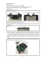
Fig. 10
•
Replacing only the receiver of the rubber antenna
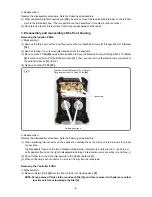
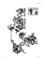
Detaching the lens plate
<<Disassembly>>
(1) Remove the four Flat Hd. Screws D2 x 4 (Black)
[54]
.
(2) Remove the Flat Metal Plate
[53]
, Lock Plate (A)
[52]
, and Lock Spring
[51]
.
(3) Bow down the Box Cover
[55]
and remove the Lens Plate
[56]
.
<<Reassembly>>
Reverse the disassembly procedure.
Replacing only the receiver of the rubber antenna
(1) Remove the screw from the joint, and then divide a new Rubber Antenna
[1]
unit into the receiver and the
main shaft.
(2) Similarly, disassemble the Rubber Antenna
[1]
mounted on the Model UR 18DSL2 by dividing it at the
joint. To disassemble the Rubber Antenna
[1]
mounted on the Model UR 18DSL2, turn the Rubber
Antenna
[1]
by 90 degrees as shown in the figure below, and then use a screwdriver to remove the screw
fixing the joint from the right side of the Model UR 18DSL2 (having a shaft at least 140 mm long). (Fig. 10)
(3) Replace the receiver of the Rubber Antenna
[1]
with a new one, and then tighten the screw fixing the
joint.
NOTE: Be careful not to lose the two thin washers mounted at the joint of the Rubber Antenna [1].
Bow down the Box Cover
[55]
and remove the Lens Plate
[56]
.
Four Flat Hd. Screws D2 x 4 (Black)
[54]
Joint Receiver
Main shaft