background image

UR 18DSL2

9 - 13

- 2 -

71

3

76

75

3

68

69

69

68

74

78

72

73

70

55

56

62

63

51

52

53

54

58

59

60

61

3

64

65

66

67

3

3

3

57

502

501

3

3

77

Summary of Contents for UR 18DSL2

Page 1: ...ODUCT NAME Hitachi Cordless Radio Model UR 18DSL2 LIST No UR 18DSL2 J862 Sep 2013 International Sales Division U TROUBLESHOOTING GUIDE 1 REPAIR GUIDE 4 STANDARD REPAIR TIME UNIT SCHEDULES 10 CONTENTS Page ...

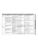
Page 2: ... 33 is blown Fuse 250 V 2 A 33 is blown Same as on the left Replace Fuse 250 V 2 A 33 Fuse 250 V 2 A 33 is not blown Go to the next check Go to check method 1 vi vi Replace Terminal Ass y E 34 and then check whether power can be turned on Power can be turned on Terminal Ass y E 34 is abnormal Replace Terminal Ass y E 34 Power cannot be turned on Controller PCBA 17 and Function PCBA 20 are abnormal...

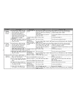
Page 3: ...res Orientation of Rubber Antenna 1 is inappropriate Move the Model UR 18DSL2 to a better reception environment e g near a window and then adjust orientation of Rubber Antenna 1 Reception is affected by noise from nearby equipment Keep the Model UR 18DSL2 away from the noise source equipment The broadcast cannot be received Go to the next check Go to check method 4 ii ii Disassemble the Model UR 1...

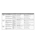
Page 4: ...can be charged The charging cable is broken Ask the customer to check whether the charging cable is broken The mobile phone cannot be charged Go to the next check Go to check method 7 ii ii Connect a normal mobile phone and then check whether the mobile phone can be charged The mobile phone can be charged The mobile phone is faulty Ask the customer to check whether the mobile phone is faulty The m...

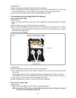
Page 5: ...g 1 from Function PCBA 20 in the front housing Then you can fully separate the front housing from the back housing Reassembly Reverse the disassembly procedure Note the following at reassembly 1 The 3 pin connectors are shaped differently to prevent wrong installation Do not forcibly connect the connectors if their shapes do not match each other The upper 3 pin connector has red black and white in...

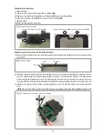
Page 6: ...crews W Flange M3 x 10 Black 9 indicated by arrows in Fig 3 and the three Machine Screws W Flange M3 x 10 Black 9 from the Jack Cover L 27 located externally on the left side You can now remove Terminal Ass y E 34 4 The Fuse 250 V 2 A 33 is located to the right of the EB battery box in Terminal Ass y E 34 and can be easily replaced Remove the five Machine Screws W Flange M3 x 10 Black 9 fixing the...

Page 7: ...emove the internal wire connected to the Rubber Antenna 1 Fig 5 4 Remove Function PCBA 20 Reassembly Reverse the disassembly procedure Note the following at reassembly 1 When soldering internal wires on the speakers carefully check the colors of internal wires for proper connections Right speakers found on the left in disassembled status Internal wire colors are red and blue Left speakers found on...

Page 8: ...8 4 Disassembly and reassembly of the external device storage case Detaching the USB PCBA Disassembly 1 Remove the four Machine Screws M4 x 15 Black 3 2 Next remove one Machine Screw M4 x 15 Black 3 on the handle arm cover side 3 Remove the two Flange Screws D3 x 6 60 on the back of the box plate 4 Cut off the wire ties and then remove the connector and the magnet Reassembly Reverse the disassembl...

Page 9: ...he main shaft 2 Similarly disassemble the Rubber Antenna 1 mounted on the Model UR 18DSL2 by dividing it at the joint To disassemble the Rubber Antenna 1 mounted on the Model UR 18DSL2 turn the Rubber Antenna 1 by 90 degrees as shown in the figure below and then use a screwdriver to remove the screw fixing the joint from the right side of the Model UR 18DSL2 having a shaft at least 140 mm long Fig...

Page 10: ... of the broadcast station and orientation of the antenna If a broadcast cannot be received well try to adjust the orientation of the FM antenna or orientation of the Model UR 18DSL2 for AM radio reception 3 Searching for a broadcast depends on the direction of the broadcast station and orientation of the antenna If a broadcast cannot be properly searched try to adjust the orientation of the FM ant...

Page 11: ...y TPE Cover A TPE Cover B Speaker Cover Back Housing TPE Cover D TPE Cover C Back Door Work Flow Function PCBA Controller PCBA Dial Speaker Back Cover Terminal D AA Battery Box Box Cover Lens Plate USB PCBA Handle Box Handle L Handle R Handle Rubber Antenna STANDARD REPAIR TIME UNIT SCHEDULES ...

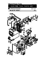
Page 12: ...el UR 18DSL2 CORDLESS RADIO LIST NO J862 2013 9 27 E1 䢢 A 32 31 9 23 29 30 28 3 38 24 33 34 9 35 36 9 25 9 26 3 3 39 27 37 9 9 25 19 14 1 2 3 4 2 5 6 7 8 9 10 11 12 13 21 15 16 17 19 19 20 3 22 3 3 19 18 A ...

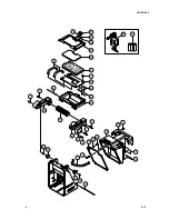
Page 13: ...UR 18DSL2 9 13 2 71 3 76 75 3 68 69 69 68 74 78 72 73 70 55 56 62 63 51 52 53 54 58 59 60 61 3 64 65 66 67 3 3 3 57 502 501 3 3 77 ...

Page 14: ...2 MODE BUTTON 1 22 331 623 TPE COVER B 1 23 334 601 SPEAKER BACK COVER 1 24 331 647 FRONT O RING 1 25 331 648 BATTERY BOX WASHER 4 26 336 293 BACK HOUSING 1 27 336 294 JACK COVER L 1 28 331 644 METAL SHAFT C 1 29 331 636 METAL SHAFT B 1 30 331 637 BUCKLE 1 31 331 639 BATTERY HOLDER COVER 1 32 331 638 BUCKLE CONNECTOR 1 33 331 650 FUSE 250 V 2 A 1 34 336 509 TERMINAL ASS Y E 1 INCLUD 33 34 336 296 ...

Page 15: ...1 656 METAL SHAFT A 1 71 331 630 ADAPTER BELT 1 72 331 631 BACK DOOR PACKING 1 73 331 632 MACHINE SCREW M2 6 X 8 BLACK 1 74 331 633 HOLDER COVER LOCKER 1 75 336 309 BACK DOOR 1 76 331 634 TPE COVER D 1 77 NAME PLATE 1 78 CAUTION LABEL 1 DESCRIPTION REMARKS 501 334 373 AC ADAPTER EURO 1 501 334 374 AC ADAPTER UK 1 501 331 987 AC ADAPTER AUST 1 502 AA BATTERY 3 4 Printed in Japan 9 13 130927N ALTERN...

Reviews: