background image

58 

Function menu


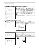
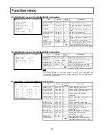
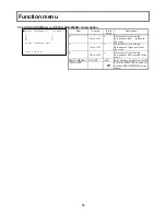
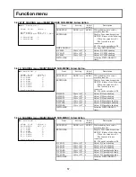
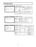
5.4.5 AUTO IRIS menu (MAINTENANCE SUB-MENU) & description. 

■AUTO IRIS  :<
 
 AUTO IRIS  :AUTO
 IRIS TRIM  :   0
 PEAK/AVE   :0/10
 IRIS GATE  :   1

 LENS FILE  :LENS 1
 IRIS SPEED :   0
 OPEN  LIMIT: 127
 CLOSE LIMIT: -85
 INITIALIZE :


Item 

Setting 

Initial 

setting 

Description 

AUTO IRIS 

REMOTE, 
AUTO 

AUTO 

Setting of Iris control mode. *1 

IRIS TRIM 

-128 to +127 

Adjust Auto iris output level 

PEAK/AVE 

0/10, 1/9, 2/8, 
3/7, 4/6, 5/5 

0/10 

Setting of Peak & Average detect 
for Auto iris 

IRIS GATE 

1 to 6 

Setting of Auto Iris gate.    *2 

LENS FILE 

LENS 1 to 8 

LENS 1  IRIS SPEED, OPEN LIMIT, and 

CLOSE LIMIT are can be stored 
to lens file. 

IRIS SPEED 

-128 to +127 

Speed control of the Iris response 

OPEN LIMIT 

0 to +127 

127 

Adjust limiter value for Auto Iris 
open 

CLOSE LIMIT  -128 to -1 

-85 

Adjust closing limiter value for 
Auto Iris 

INITIALIZE 


Initialize auto iris menu 


*1: Effect only AUTO selected at the lens side selection switch. If it

’s selected to MANUAL, drive iris 

directly. 

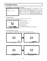
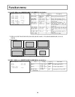
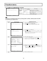
*2: IRIS GATE 

1

2

3

4

5

6


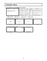
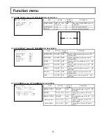
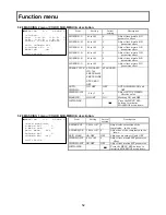
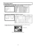
5.4.6 MIC GAIN menu (MAINTENANCE SUB-MENU) & description. 

■MIC GAIN   :<
 
 MIC1       :-60 dB
 MIC2       :-60 dB

 FRONT MIC
  PHANTOM    :OFF


Item 

Setting 

Initial 

setting 

Description 

MIC 1 

-70,-60,-50,-40, 
-30,-20,-10 

-60dB 

Set input gain of MIC1 

MIC 2 

-70,-60,-50,-40, 
-30,-20,-10 

-60dB 

Set input gain of MIC2 

FRONT MIC 
      PHANTOM 

ON,OFF 

OFF 

Fantom power ON and OFF 


Summary of Contents for SK-HD1800

Page 1: ...HD COLOR CAMERA SK HD1800 OPERATING INSTRUCTIONS Please read these operating instructions carefully for proper operation and keep them for future reference ...

Page 2: ...e important for you to keep for your convenience and protection These numbers appear on the nameplate located on bottom of the product Please record these numbers in the spaces provided below and retain this manual for future reference Model No Serial No ...

Page 3: ...全事项以及使用上应注意的问题 从制造日 起到此年限内 不会发生产品中的有害物质外泄 突变等 不会对环境 人体以及财产产生 严重影响 同时 此年限是除去必须定期交换的保守部品的 是其他产品的环保使用期限 产品在正常情况下使用完毕要废弃时 请遵守各地区对电子信息产品的回收 再利用的相关 各项法律 法规 另外 从第三者处转买的情况下即使在本期限内也视为失去效力 2 产品中有毒有害物质或元素的名称及含量 部件名称 有毒有害物质或元素 铅 Pb 水银 Hg 镉 Cd 六价铬 Cr VI 多溴 联苯 PBB 多溴 二苯醚 PBDE 1 主机 表示该有毒有害物质在该部件所有均质材料中的含量均在 SJ T11363 2006 标准规定 的限量要求以下 表示该有毒有害物质至少在该部件的某一均材料中的含量超出 SJ T11363 2006 标准 规定的限量要求 COLOR CAMERA ...

Page 4: ......

Page 5: ...e to equipment Caution notes indicate any condition or practice which if not strictly observed or remedied could result in damage or destruction of the equipment NOTE Notes indicate an area or subject of special merit emphasizing either the product s capabilities or common errors in operation or maintenance WARNING TO REDUCE THE RISK OF FIRE OR ELECTRIC SHOCK DO NOT EXPOSE THIS COLOR CAMERA TO RAI...

Page 6: ...nation should be moved with care Quick stops excessive force and uneven surfaces may cause the product and cart combination to overturn 10 Ventilation Slots and openings in the cabinet are provided for ventilation and to ensure reliable operation of the product and to protect it from overheating and these openings must not be blocked or covered The openings should never be blocked by placing the p...

Page 7: ...ervice personnel under the following conditions a When the power supply cord or plug is damaged b if liquid has been spilled or objects have fallen into the product c If the product has been exposed to rain or water d If the product does not operate normally by following the operating instructions Adjust only those controls that are covered by the operating instructions as an improper adjustment o...

Page 8: ...agen sollte vorsichtig bewegt werden Schneller Halt übermäßige Krafteinwirkung und unebene Oberflächen können Umkippen der kombination von Erzeugnis und Wagen verursachen 10 Ventilation Schlitze und Öffnungen im Gehäuse dienen der Ventilation Sie sind für zuverlässigen Betrieb des Gerätes und Schutz vor Überhitzung erforderlich und dürfen nicht blockiert oder abgedeckt werden Die Öffnungen sollten...

Page 9: ...orliegt a Wenn das Netzkabel oder der Stecker beschädigt ist b Bei Eindringen von Flüssigkeit oder Fremdkörpern in das Gerät c Wenn das Erzeugnis Regen oder Wasser ausgesetzt worden ist d Wenn das Erzeugnis bei Befolgen der Bedienungsanleitungen nicht normal funktioniert Nur die Regelelemente verstellen die in den Bedienungsanleitungen behandelt werden da unangemessene Einstellung anderer Regelele...

Page 10: ... arrêts brusques une force excessive et des surfaces irréguliéres pourraient provoquer le renversement de l ensemble appareil chariot 10 Ventilation Les fentes et les ouvertures du coffret sont prévues pour la ventilation ainsi que pour garantir un fonctionnement en toute sécurité de l appareil et le protéger de toute surchauffe et ces ouvertures ne devront donc être ni obstruées ni recouvertes Ne...

Page 11: ... le cordon d alimentation ou sa fiche sont endommagés b Si du liquide s est renversé sur l appareil ou que des objets sont tombés dedans c Si l appareil a été exposé á la pluie ou á l eau d Si l appareil ne fonctionne pas normalement lorsqu on observe les instructions d utilisation Ne régler que les commandes couvertes par le mode d emploi en effet un réglage incorrect des autres commandes pourrai...

Page 12: ... improvement Confirm the most recent specifications at time of order Hitachi Kokusai Electric certifies this product complies with the standard warranty conditions of Hitachi Kokusai Electric and that quality control is implemented to the extent required to comply with those conditions Warranty and service 1 The guarantee period is one year after the data purchase However the defects due to errone...

Page 13: ...hading adjustment 14 Tripod mounting 17 Viewfinder adjustment 18 Viewfinder indications 20 Filter selection 21 White and black balance adjustment 22 Electronic shutter setting 27 Setup card 29 Function menu 36 Specifications 67 Studio system operation 72 Service information 73 Application note Connecting prompter power 75 Notice for a studio box lens use 76 ...

Page 14: ......

Page 15: ...ens iris and shutter speeds Setup card A small plug in setup card SD card stores the user setup and Scene File information Digital processing improves Image Highlight Quality Real time Lens Aberration Correction RLAC Lens chromatic aberration of magnification is reduced by digital processing with supporting lenses Knee saturation and auto knee The auto knee provides a wide dynamic range by dynamic...

Page 16: ...t when color bars are selected Microphone input accepts phantom power supply Viewfinder displays Two mode zebra Menu selection of over level or between range zebra is provided Safety zone and center mark display Focus assist indicator is displayed on a view finder to help adjust focus position Auto focus lens area marker can be displayed High performance viewfinder VF 402 2 inch black and white CR...

Page 17: ...ng and disconnecting A lens microphone and other cables grasp the connector by the body not the attached cable Cables can be damaged by pulling on them Note when transporting When transporting by hand use the carrying case If shipping by truck or other means pack in the carrying case then use further cushioning and pack in a sturdy carton Tripod Use a recommended tripod and install the camera corr...

Page 18: ...for handling 1 Cable Connector Receptacle 1 FCF Fiber Cable Female 2 FCM Fiber Cable Male 3 FCFR Female Receptacle 4 FCMR Male Receptacle 2 Maintenance tool information 1 Cleaning Stick CANARE CLETOP 2 5 2 0 2 CLEANING KIT Fiber optical cable assembly manufacture CANARE has Cleaning kit for the optical fiber cable connector available Detail is in URL http www canare co jp ...

Page 19: ... card Slot for inserting setup card MAX 2GB A5 Shoulder pad A6 Viewfinder attachment A7 Shoulder belt hook Attachment for separately sold shoulder belt A8 CALL button Press to call the CCU A9 POWER switch Power is supplied from external unit via DC power connector F1 Refer to page 11 EXT Power supplied via DC input connector CCU Power supplied via fiber cable Power is supplied from CCU Camera Cont...

Page 20: ...nal of channel1 on off button While pressing this button HD SDI output from MON RET output connector and the picture on view finder can be switched to return picture B6 CCU connector Connector for fiber optic cable B7 AC230V OUT connector Maximum 100VA AC230V can be supplied to external unit For detail Refer to page 75 B8 HD SDI2 connector BNC CA HF1000 HD SDI output CA HF1200 3G HD SDI output CX ...

Page 21: ...tch AWB AWB Automatic White Balance can be executed by lifting up the switch Please set WHITE BAL switch D7 to A or B before executing AWB ABB ABB Automatic Black Balance can be executed by pushing down the switch C5 INCOM MIC on off button Intercom microphone can be used while pressing this button when switch E8 on camera adaptor shown page 10 is set to FRONT C6 INCOM LEVEL control Intercom recei...

Page 22: ...O KNEE ON Camera mode with AUTO KNEE on D7 WHITE BAL switch PRE The white balance is set to the memory value for 3200K A or B When the AUTO W B BAL switch C4 is set to AWB the white balance is adjusted automatically D8 CS 1 CHECK switch CHECK Viewfinder displays camera operating data such as switch status recording elapsed time and audio level CS 1 A function assigned in the CUSTOM SW menu can be ...

Page 23: ...nal video sources input to CCU These four signals can be assigned by CCU menu E5 RET 1 2 switch Selects RET 1 RET 2 input Selected return video is displayed on view finder while this button is pressed CH1 CH2 CH3 CH4 RET 1 1080p 1080i 720p SD SDI 16 9 or SD SDI 4 3 RETURN ASSIGNMENT CCU MENU INPUT SELECT CCU MENU CCU CU HD1000 CAMERA RET1 CH1 CH2 CH3 CH4 RET2 RET 2 1080p 1080i 720p SD SDI 16 9 or ...

Page 24: ... receive level can be adjusted with E7 Lower FRONT MIC mode Intercom microphone works while C5 is pressed Intercom receive level can be adjusted with C6 E9 INCOM 1 2 PD ENG select switch This switch is used to select the PD or ENG input of the external intercom system to be connected to the CCU rear side E10 INTERCOM 1 INTERCOM 2 connector XLR 5 pin Intercom headset can be connected E11 SCRIPT con...

Page 25: ...phone or rear microphone1 The front microphone connector or rear microphone connector microphone can be selected F3 MIC1 MIC2 connector XLR 3 pin Connector for microphone F4 MIC LINE OFF 48V switch LINE For a line level signal source OFF Not to supply a power 48V To supply a power of 48VDC F5 HD SDI 1 output connector BNC HD SDI signal output F1 4 F2 4 F4 4 F5 4 F3 4 ...

Page 26: ...he following adjustments may be required according to the type of lens 1 Lens flange back 2 Lens white shading 3 Lens auto iris speed 4 Lens iris close limit AUTO IRIS menu Refer to the lens instructions when using the lens 1 RET switch RET1 ON OFF selected by RET1 SEL in the camera adapter Refer to page 9 2 VTR switch Work for TALK or RET 2 function with CUSTOM SW MENU setting TALK INCOM TALK ON ...

Page 27: ...ters distant 3 Open the iris and adjust the lighting to obtain the correct video output level If the video level is too high use a ND filter or electronic shutter 4 Loosen the FB ring setscrew 5 By hand or motor set the zoom ring to the telephoto position 6 Observe the flange back chart image and turn the distance ring to adjust the focus 7 Set the zoom ring to the wide angle position 8 Turn the F...

Page 28: ... on the camera Be sure to connect the lens cable 2 Turn the electronic shutter off and set the gain to L 0 dB 3 Shoot a whole white object like cloth or wall if possible use chart viewer of Esser or Porta Pattern without shading 4 Set the lens extender to OFF 5 When notice flicker on the monitor which occurred by fluorescent or mercury lighting use sunlight or halogen as the light source Using aut...

Page 29: ... MENU SELECT button for about 1 second to adjust white shading The viewfinder top and bottom cursors flash to indicate automatic white shading adjustment in progress The cursors extinguish at the end of adjustment cursors 9 Set the extender if provided to on and repeat the above step 10 Close the Function menu White shading adjustment is completed by the above The adjustment is stored in a nonvola...

Page 30: ...tall the camera adapter option Installation 1 Align the adapter guide pin with the camera guide shoe Press to insert the adapter 2 Tighten screws 1 2 and 3 to secure the camera adapter CAUTION Tighten screws fully to prevent wobble between adapter and camera 1 2 3 ...

Page 31: ...dicated by the arrow A click sound can be heard at the locked position 3 Slightly loosen the tripod screw and again check the balance Shift the adapter to the optimum position and securely tighten the tripod screw Detaching Press the red lock pin and turn the lever in the arrow direction Remove the camera CAUTION 1 The weight can exceed 5kg with the lens and 10kg with a VTR Use a sturdy tripod tha...

Page 32: ... 1 Turn the lock lever in the arrow direction to loosen the horizontal lock 2 Turn the lock screw in the arrow direction to loosen the front to rear lock 3 Adjust the viewfinder left to right and front to rear positions for comfortable viewing 4 Tighten the lock screw firmly 5 Tighten the lock lever securely Eyepiece angle adjustment 1 Turn and loosen the securing ring 2 Adjust the eyepiece vertic...

Page 33: ... not using the eyecup it can be raised out of the way while pressing the flip up button WARNING 1 When the hood is raised do not look at the sun or other bright light through and eyepiece lens There is danger of eye damage 2 When the hood is raised do not place the camera where sunlight can pass through the eyepiece lens There is risk of damage to the camera and peripheral equipment as well as a h...

Page 34: ...ender Shutter speed Focus position Zoom position ND Filter ECC Filter Iris F stop Master gain Display description Item Description Extender No indication E Either of the following When the extender is X1 The lens cable is not connected When the extender is X2 Shutter OFF 1 100 NTSC or 1 60 PAL 1 125 1 250 1 500 1 1000 1 2000 1 60 37 to 1 1987 NTSC 1 50 36 to 1 2025 PAL AES OFF PRESET LOCK SCAN Aut...

Page 35: ... the scene lighting source The correct optical filter according to the scene light source needs to be selected in order to obtain correct white balance Operation method Filter No Mode operation ND Filter 1 2 3 4 Clear Cross 1 16 ND 1 64 ND 1 2 3 4 FILTER ND button ECC Filter A B C D E 3200 K 4300 K 5600 K 6300 K 8000 K A B C D E FILTER ECC button ...

Page 36: ... selection switch the new setting status will be indicated in the viewfinder for about 3 seconds 3 Place a white pattern at a location subject to the same lighting conditions as the scene Use zoom function of the lens so that the screen is white A white object e g cloth wall placed near the scene of interest can be used provided the size is adequate see figure Note Use care a high luminosity light...

Page 37: ...t white balance adjustment AUTO WHITE NG LEVEL HIGH TRY AGAIN Excessive lighting for adjustment Set the GAIN switch to a lower position In case the manual iris is using at the lens adjust the iris stop of the lens Then repeat white balance adjustment AUTO WHITE NG C TEMP HIGH CHANGE FILTER TRY AGAIN Color temperature adjustment is too high Change ECC filter and readjust AUTO WHITE NG C TEMP LOW CH...

Page 38: ...arge change of ambient temperature Gamma setting changed 1 Set the AUTO W B BAL switch to ABB for automatic black balance adjustment 2 The viewfinder displays the following messages during adjustment The lens iris is automatically closed 3 Adjustment is completed in several seconds and automatically stored in memory AUTO BLACK Adjustment in progress AUTO BLACK OK Adjustment complete AUTO W B BAL s...

Page 39: ...remote controller is pressed again the auto black will be executed even if a tally is on When press the auto black button again please make sure the situation AUTO BLACK NG TRY AGAIN Range is exceeded cannot adjust See Note 2 Note2 The lens iris is automatically closed during black balance adjustment If the iris control is manual open the iris after adjustment Check the lens connection If ok fault...

Page 40: ...nder as an auto set up result Message Cause CHANGE TO CAM Error Change Bar to CAM NOT GRAYSCALE Not in the gate marker or no gray chart SETUP OK Finish set up BLACK OK Finish set up BLACK NG M BLACK Master black setup error GAIN GAMMA FLARE NG R R CH error GAIN GAMMA FLARE NG G G CH error GAIN GAMMA FLARE NG B B CH error GAIN GAMMA FLARE NG R G R G CH error GAIN GAMMA FLARE NG R B R B CH error GAI...

Page 41: ...el when the light is greater than the close limit Shutter mode and speed settings 1 Shift the Shutter switch from ON to SEL to change the shutter speed The viewfinder screen indicates speed change and new shutter speed Example 1 100 2 The mode and speed change sequence is indicated below SHUTTER SCENE 0 SHUTTER OFF SHUTTER PRE 1 100 SHUTTER VAR 1 60 37 INITIALIZE SHUTTER OFF PRESET VARIABLE AES SH...

Page 42: ...ove the cursor to SHUTTER VAR Adjust the rotating MENU SEL KNOB buttons SHUTTER SCENE 0 SHUTTER OFF SHUTTER PRE 1 100 SHUTTER VAR 1 60 37 INITIALIZE 3 The image of a computer screen having a different scanning frequency includes a light or dark bar rolling up or down through the image Adjust the rotating MENU SEL KNOB buttons to minimize the bar F lic k e r fre e im a g e S lo w s h u tte r s p e ...

Page 43: ...e the miniSD cards in the camera always install the adapter specially designed for miniSD cards The unit will not work properly if only adapter is installed Make sure that the card has been installed in the adapter before using it Removal Press the setup card for rejection CAUTION Avoid the following when handling the setup card High temperature and humidity Water drops Electric fields Notes When ...

Page 44: ...check results are normal with system operation the SETUP CARD menu appears in the viewfinder CHECKING CARD SETUP CARD MENU FILE DATE TIME VF 1 VF 2 VF 3 VF 4 VF 5 ALL CLEAR PUSH 1SEC When the check results are normal with control head function the SETUP CARD menu appears in the viewfinder CHECKING CARD SETUP CARD VF FILE DATE TIME VF 1 VF 2 VF 3 VF 4 VF 5 ALL CLEAR PUSH 1SEC When the check results...

Page 45: ...ations other than formatting SETUP CARD MENU NOT FORMATTED FORMAT PUSH 1SEC Removing the setup card while the SETUP CARD menu is being indicated displays the following SETUP CARD MENU NO CARD Insert the setup card while this menu is being indicated status pass to CHECKING CARD display menu Note The checking time depends on a particular setup card inserted Note If it is attempted to open the functi...

Page 46: ... VF 1 LOAD FILE PUSH 1SEC SAVE FILE PUSH 1SEC CLEAR FILE PUSH 1SEC CCU side monitor displays in system operation mode SETUP CARD VF FILE DATE TIME VF 1 VF 2 VF 3 VF 4 VF 5 ALL CLEAR PUSH 1SEC SELECT FILE FILE NAME VF 1 LOAD FILE PUSH 1SEC SAVE FILE PUSH 1SEC CLEAR FILE PUSH 1SEC SETUP CARD SYS FILE DATE TIME SYS 1 SYS 2 SYS 3 SYS 4 SYS 5 ALL CLEAR PUSH 1SEC SELECT FILE FILE NAME SYS 1 LOARD FILE P...

Page 47: ...VF 1 LOAD FILE PUSH 1SEC SAVE FILE PUSH 1SEC CLEAR FILE PUSH 1SEC SELECT FILE FILE NAME VF 1 SAVING LOAD FILE PUSH 1SEC SAVE FILE PUSH 1SEC CLEAR FILE PUSH 1SEC 3 The load save or clear results appear SELECT FILE FILE NAME VF 1 LOAD OK LOAD FILE PUSH 1SEC SAVE FILE PUSH 1SEC CLEAR FILE PUSH 1SEC SELECT FILE FILE NAME VF 1 SAVE OK LOAD FILE PUSH 1SEC SAVE FILE PUSH 1SEC CLEAR FILE PUSH 1SEC SELECT ...

Page 48: ... FILE PUSH 1SEC CARD OK Formatted Format OK No format Remove card Remove card Remove card Insert card Select file 2 Camera system menu operation from the RU at CCU side monitor display in the Monitor SETUP CARD MENU NOT FORMATTED FORMAT PUSH 1SEC CHECKING CARD SETUP CARD MENU NO CARD CARD OK Formatted Format OK No format Remove card Remove card Remove card Insert card Select file SETUP CARD MENU F...

Page 49: ...C CLEAR FILE PUSH 1SEC SETUP CARD VF FILE DATE TIME VF 1 VF 2 VF 3 VF 4 VF 5 ALL CLEAR PUSH 1SEC SETUP CARD SYS FILE DATE SYS 1 08 07 24 11 11 SYS 2 SYS 3 SYS 4 SYS 5 ALL CLEAR PUSH 1SEC Select file SELECT FILE FILE NAME SYS 1 LOAD FILE PUSH 1SEC SAVE FILE PUSH 1SEC CLEAR FILE PUSH 1SEC In event of error If setting data save or load or setup card format results are erroneous the setup card may be ...

Page 50: ... view finder by pressing this button The menu describes the camera functions and structure with multiple pages First page of structure is named Top menu This Top menu screen is appeared ON and disappeared OFF by pressing this MENU BUTTON Top Menu Display in the viewfinder or the PIX monitor Top menu has three kind status screens depend on the camera operation and the monitoring location and detail...

Page 51: ...menu Move the cursor with rotating the knob then press the MENU SEL knob First line of sub menu has the cursor and or marker The marker indicate additional sub menu Press the MENU SEL knob again and next sub menu screen is shown up The marker indicate no additional sub menu behind This indicate can go back to main menu with pressing the MENU SEL knob Some control items in sub menu has marker on ri...

Page 52: ...en this menu by pushing the MENU SW in the RCU From the RU control unit all function controls can give to the camera head and set the camera function at head site which we call CONTROL HEAD and display in the Viewfinder as follows TOP MENU VF COLOR DETAIL MAINTENANCE FILE CUSTOM SW SETUP CARD VF MENU All above TOP MENU has following Main menu Item Main Menu Description 1 VF Change screen to VF mai...

Page 53: ...OFF HIGH LEVEL 75 LOW LEVEL 60 MARKER1 SEL USER 1 CENTER MARK ON SAFETY MARK ON SIDE 4 3 OFF 13 9 OFF 14 9 OFF 15 9 OFF CROSS OFF BOX1 OFF BOX2 OFF MARKER2 SEL USER 1 CENTER MARK OFF SAFETY MARK OFF SIDE 4 3 OFF 13 9 OFF 14 9 OFF 15 9 OFF CROSS OFF BOX1 OFF BOX2 OFF CROSS SET USER 1 H POSITION 5 V POSITION 5 BOX1 SET USER 1 H POSITION 30 V POSITION 25 H SIZE 15 V SIZE 10 BOX2 SET USER 1 H POSITION...

Page 54: ... 0 0 C 0 0 Y R 0 0 B C 0 0 Y 0 0 B 0 0 G Y 0 0 M B 0 0 G 0 0 M 0 0 C G 0 0 R M 0 0 MASKING OFF INITIALIZE MASKING 2 SCENE 0 LINEAR R G 19 G R 1 B R 0 R B 3 G B 3 B G 6 PRESET TYPE STANDARD AUTO CHROMA OFF A CHROM LEV 0 MASKING ON INITIALIZE MASKING 3 SCENE 0 SKIN MASKING S MASK SAT 0 S MASK HUE 0 SKIN MASK OFF CHROMA SAT 0 CHROMA SAT OFF INITIALIZE GAMMA 1 SCENE 0 R GAMMA 0 G GAMMA 0 B GAMMA 0 TOT...

Page 55: ...INITIALIZE SKIN DTL 2 SCENE 0 THRESHOLD 96 SKIN DETAIL OFF SKIN GATE OFF GATE IND 1ch ZOOM DEPEND OFF SENS 50 RANGE 50 INITIALIZE HIGH CHROMA SCENE 0 R 0 G 0 B 0 HIGH CHROMA OFF INITIALIZE MAIN MENU SUB MENU Typical picture for explaining of DTL functions CH1 CH2 A PHASE adjustment H DTL Signal V DETAIL H CRISP Adjust Best noise performance V CRISP Adjust Best noise performance LEVEL DEP H GAIN P ...

Page 56: ...00 SHUTTER VAR 1 60 37 INITIALIZE SYSTEM CAMERA ID 1 FAN MODE AUTO GL H PHASE 512 SDI AUDIO OFF BAR TONE OFF MON RET OUT MONITOR TIME DATE CHECK 1 TEST OFF GAMMA ON DETAIL ON MASKING OFF KNEE ON CHECK 2 MODEL SK HD1800 CPU Ver Check SUM VIDEO Ver IF Ver CA Ver GAIN CUSTOM STEP LESS OFF SPEED SLOW M GAIN LOW 0 dB M GAIN MID 6 dB M GAIN HIGH 12 dB MIC GAIN MIC1 60 dB MIC2 60 dB FRONT MIC PHANTOM OFF...

Page 57: ...E WHT SHADING LENS FILE LENS 1 EXTENDER OFF 1 WHT SHADING PUSH 1SEC H SHADING V SHADING H SHADING LENS FILE LENS 1 EXTENDER OFF 1 R H SAW 0 G H SAW 0 B H SAW 0 R H PARA 0 G H PARA 0 B H PARA 0 INITIALIZE V SHADING LENS FILE LENS 1 EXTENDER OFF 1 R V SAW 0 G V SAW 0 B V SAW 0 R V PARA 0 G V PARA 0 B V PARA 0 INITIALIZE REGI R REGI H 0 B REGI H 0 G REGI H Ref R REGI V 0 B REGI V 0 G REGI V Ref IRIS ...

Page 58: ... OFF VF Detail ON and OFF DTL LEVEL 128 to 127 0 Adjust VF detail level CRISP 128 to 127 80 Adjust VF detail Crisp Note When VF L90HD is used VF DTL LEVEL is controlled in Peaking volume of the viewfinder 5 1 2 VF MARKER menu VF SUB MENU description VF MARKER USER SEL USER 1 MARKER1 SEL MARKER2 SEL CROSS SET BOX1 SET BOX2 SET OTHER SET MARKER1 SW ON MARKER2 SW OFF Item Setting Initial setting Desc...

Page 59: ...x1 marker ON and OFF BOX2 ON OFF OFF Box2 marker ON and OFF Note This safety marker is synchronized with aspect ratio 4 3 13 9 14 9 15 9 OFF 16 9 of the Side panel 5 1 2 2 CROSS SET menu VF SUB MENU description CROSS SET USER 1 H POSITION 5 V POSITION 5 Item Setting Initial setting Description H POSITION 0 to 255 5 Adjust Vertical line of Cross Marker horizontally V POSITION 0 to 255 5 Adjust hori...
Page 60: ... setting of center marker 3 SAFTY MARK TYPE1 2 3 TYPE1 2 Type setting of safety marker 4 SAFTY AREA 80 0 90 0 92 5 95 0 90 0 Setting of safety area MARKER LEV 0 to 100 100 Adjustment of marker level 1 USER 1 TYPE 1 USER 2 TYPE 2 USER 3 TYPE 3 USER 4 TYPE 4 2 USER 1 TYPE 1 USER 2 TYPE 2 USER 3 TYPE 3 USER 4 TYPE 1 3 Type setting of center marker TYPE 1 TYPE 2 TYPE 3 TYPE 4 4 Type setting of safety ...

Page 61: ...ter indicator in VF ON and OFF ZOOM ON OFF OFF Display the Zoom indicator in VF ON and OFF FOCUS ON OFF OFF Display the Focus indicator in VF ON and OFF FILER ON OFF ON Display the Filter indicator in VF ON and OFF M GAIN ON OFF OFF Display the M Gain indicator in VF ON and OFF IRIS ON OFF ON Display the Iris indicator in VF ON and OFF 5 1 5 VF ZEBRA menu VF SUB MENU description VF ZEBRA ZEBRA TYP...
Page 62: ...dicator is the focal position FOCUS ASSIST INDICATOR un focus focus FOCUS ASSIST MARKER PEAK HOLD MARKER FOCUS ASSIST MARKER Integration area of picture edge level FOCUS ASSIST INDICATOR Integration value of picture edge PEAK HOLD MARKER Peak value position marker The peak hold marker remains for 4 sec on the screen This marker shows the target level of the just focal posision Focus assist indicat...

Page 63: ...to 127 0 Adjust Green Gain B GAIN 128 to 127 0 Adjust Blue Gain VIDEO CTEMP 1600K to 15500K 3200K Adjust Color temperature INITIALIZE Press the MENU SEL buttons to initialize GAIN menu items 5 2 2 BLACK FLARE COLOR SUB MENU description BLACK FLARE SCENE 0 R BLACK 0 G BLACK 0 B BLACK 0 R FLARE 0 G FLARE 0 B FLARE 0 FLARE ON M BLACK 0 INITIALIZE Item Setting Initial setting Description R BLACK 128 t...

Page 64: ... OFF OFF HDR ON and OFF HDR SELECT HLG600 HLG1200 HPQ HLG600 Select HDR mode BLK STR LEV 0 to 11 0 Select gamma curve value from table BLK STRETCH ON OFF OFF Black Stretch ON and OFF INITIALIZE Press the MENU SEL buttons to initialize GAMMA2 menu items Note1 Create high quality of picture user can choose fixed gamma curve from table and also Black Stretch BLK STR function bring out detail from dar...

Page 65: ...E CLIP ON OFF ON White Clip function ON and OFF INITIALIZE Press the MENU SEL buttons to initialize KNEE CLIP2 menu items Note Very bright portion of high light scene is reduced color saturation and changed hue This Knee Saturation compensates this effect and makes more natural color reproduction 5 2 7 MASKING 1 COLOR SUB MENU description MASKING 1 SCENE 0 HUE SAT HUE SAT R 0 0 C 0 0 Y R 0 0 B C 0...

Page 66: ... 709 SMPTE 240M SMPTE WIDE NTSC EBU OFF STANDARD AUTO CHROMA ON OFF OFF AUTO CHROMA ON and OFF CHROMA SAT 8 to 7 0 Adjust AUTO CHROMA effective value MASKING ON OFF ON Masking ON and OFF INITIALIZE Press the MENU SEL buttons to initialize MASKING2 menu items 5 2 9 MASKING 3 menu COLOR SUB MENU description MASKING 3 SCENE 0 SKIN MASKING S MASK SAT 0 S MASK HUE 0 SKIN MASK OFF CHROMA SAT 0 CHROMA SA...

Page 67: ... 110 Adjust V detail crisp LEVEL DEP 128 to 127 50 Adjust level dependent of detail DTL FREQ 13 14 15 16 17 18 19 17 MHz Set boost frequency of detail DETAIL ON OFF ON Detail On and OFF INITIALIZE Press the MENU SEL buttons to initialize DETAIL 1 menu items 5 3 2 DETAIL 2 menu DETAIL SUB MENU description DETAIL 2 SCENE 0 D KNEE WHT 105 D KNEE BLK 110 DETAIL KNEE ON P N BALANCE 8 8 KNEE DETAIL 50 D...

Page 68: ...same functions in the AUTO SETUP menu and can be accessed from either menu Refer to page 56 5 3 4 SKIN DTL 2 menu DETAIL SUB MENU description SKIN DTL 2 SCENE 0 THRESHOLD 96 SKIN DETAIL OFF SKIN GATE OFF GATE IND 1ch ZOOM DEPEND OFF SENS 50 RANGE 50 INITIALIZE WIDE TELE LENS ZOOM POSITION Detail level at skin color SENS RANGE SKIN TONE DTL OFF Smoothest ZOOM DEPEND description Item Setting Initial...

Page 69: ...R 128 to 127 0 Adjust detail level in high chrominance Red portion in the scene G 128 to 127 0 Adjust detail level in high chrominance Green portion in the scene B 128 to 127 0 Adjust detail level in high chrominance Blue portion in the scene HIGH CHROMA ON OFF OFF High Chroma detail ON and OFF INITIALIZE Press the MENU SEL buttons to nitialize HIGH CHROMA menu items ...

Page 70: ...ge screen to OTHERS menu CHECK Change screen to CHECK menu 5 4 1 AUTO SETUP menu MAINTENANCE SUB MENU description AUTO SETUP CH1 A PHASE PUSH 1SEC CH2 A PHASE PUSH 1SEC GRAY SCALE PUSH 1SEC BLACK LEV 5 00 FLARE LEV 12 00 GAMMA LEV 58 00 Item Setting Initial setting Description CH1 A PHASE Skin tone Auto CH1 phase set 1 CH2 A PHASE Skin tone Auto CH2 phase set 1 GRAY SCALE Gray scale Auto set up 2 ...

Page 71: ...he following When the extender is X1 The lens cable is not connected X2 When the extender is X2 R H SAW 128 to 127 0 Adjust R H saw shading G H SAW 128 to 127 0 Adjust G H saw shading B H SAW 128 to 127 0 Adjust B H saw shading R H PARA 128 to 127 0 Adjust R H parabpla shading G H PARA 128 to 127 0 Adjust G H parabpla shading B H PARA 128 to 127 0 Adjust B H parabpla shading INITIALIZE Initialize ...

Page 72: ... OPEN LIMIT and CLOSE LIMIT are can be stored to lens file IRIS SPEED 128 to 127 0 Speed control of the Iris response OPEN LIMIT 0 to 127 127 Adjust limiter value for Auto Iris open CLOSE LIMIT 128 to 1 85 Adjust closing limiter value for Auto Iris INITIALIZE Initialize auto iris menu 1 Effect only AUTO selected at the lens side selection switch If it s selected to MANUAL drive iris directly 2 IRI...

Page 73: ... INITIALIZE Item Setting Initial setting Description SHUTTER OFF PRESET VAR AES OFF SHUTTER PRE 1 100 59 94i 1 60 50i 1 125 1 250 1 500 1 1000 1 2000 1 100 59 94i 1 60 50i SHUTTER VAR 1 60 37 1 1987 59 94i 1 50 36 1 2025 50i 1 60 37 59 94i 1 50 36 50i INITIALIZE 5 4 9 SYSTEM menu MAINTENANCE SUB MENU description SYSTEM CAMERA ID 1 FAN MODE AUTO GL H PHASE 512 SDI AUDIO OFF BAR TONE OFF MON RET OUT...

Page 74: ...Move the cursor to SYSTEM FREQ 3 Press button to change from 59 94Hz to 50Hz FORMAT SYSTEM FREQ 50Hz SET DATA PUSH 4 Move the cursor to SET DATA 5 Press button for two seconds to establish system frequency of camera Menu screen will be disturbed inevitably due to frequency collision between camera and CCU RU 6 Turn off the camera power CCU CU FUNCTION BUZZER ENABLE SDI AUDIO OFF CCU ID 1 CABLE MOD...

Page 75: ...u MAINTENANCE SUB MENU description CHECK 2 MODEL SK HD1800 CPU Ver Check SUM VIDEO Ver IF Ver CA Ver Item Description MODEL Camera model name CPU CPU software version Check SUM CPU software check sum VIDEO Ver FPGA version on VIDEO board IF Ver FPGA version on IF board CA Ver FPGA version in camera adaptor 5 4 13 RLAC menu RLAC RLAC OFF STATUS ENABLE Item Setting Initial setting Description RLAC O...

Page 76: ...REGI Item Setting Initial setting Description LENS FILE LENS 1 to 8 LENS 1 Selection of lens file setting AUTO IRIS Change screen to AUTO IRIS WHT SHADING Change screen to WHT SHADING Same as that of the MAINTENANCE menu REGI Change screen to REGI Note Lens file items are stored to the selected lens file automatically when the setting is changed So change to another lens file at exchanging a lens ...

Page 77: ...CENE FILE 0 SCENE FILE 0 SCENE FILE 0 SCENE FILE 0 SCENE FILE 0 SCENE FILE 0 LENS FILE 1 1 The SCENE FILE is indicated at top right corner in the each menu in the FUNCTION menu 2 The COMMON FILE and the TEMPORARY SCENE FILE data values are stored to the memory automatically When the SCENE FILE 0 is selected adjusted value data is stored to memory automatically 3 SCENE 1 to 8 After selected scene f...

Page 78: ...A MARKER VF DTL QUICK FOCUS FAW ZEBRA Set CS 1 switch CA CS SW VF DTL MARKER1 MARKER2 Set CS switch in the CA LENS VTR SW RET 2 TALK TALK Set VTR switch in the Lens INCOM SW INCOM1 INCOM2 INCOM1 2 INCOM1 Assign INCOM microphone ON OFF switch Note Quick Focus automatically opens the iris then sets the video level with the electric shutter With the resulting shallow depth of focus the exact focus po...

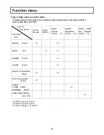
Page 79: ... RU 1500 Type of Auto Setup Controlled item AUTO BLACK AUTO WHITE GRAY SCALE AUTO 1 WHITE SHADING AUTO 2 SKIN TONE DTL PHASE AUTO 3 BLACK R G B GAIN R B GAMMA R G B FLARE R G B BLACK H SHADING R G B Pixel Concealment R G B WHITE V SAW H SAW SHADING R G B SKIN TONE PHASE CH1 CH2 1 Refer to page 26 and 56 2 Refer to page 14 and 56 3 Refer to page 41 54 and 56 ...

Page 80: ... when shooting bright scene some porting of the picture may have washed out effect Knee Saturation function can be improved this effect 4 MASKING 3 Skin masking When the SK HD1800 chain is used for the newscast program newscaster flesh tone color can be changed to natural complexion by this function Luminance clarity improvement function 1 GAMMA TABLE The selectable gamma table provided with SK HD...

Page 81: ...24 dB 13 Shutter 1 100 1 125 1 250 1 500 1 1000 1 2000 second 59 94i 1 60 1 125 1 250 1 500 1 1000 1 2000 second 50i 14 Lock scan 1 60 37 to 1 1987 second 59 94i scan 1 50 36 to 1 2025 second 50i scan 15 Geometric distortion Negligible excluding lens characteristics 16 Registration Overall 0 01 excluding lens characteristics 17 Dimensions 133 W x 191 H x 262 D mm 18 Power supply voltage DC 12 V 10...

Page 82: ...email connector LEMO Tajimi Type SMPTE304M type 2 Fiber adaptor I O 1X BNC HD SDI1 OUT HD SDI 1080p 1X BNC HD SDI2 OUT HD SDI 1080i RET B OUT switch able HD SDI 1080p 1X BNC PROMPT switch able GENLOCK analog Tri level in or SD VBS OUT 5 pin Script 12VDC OUT 1 0A max 29 pin D SUB for studio adaptor 5 pin AC230V for Prompter Power Tally out 2X XLR INCOM 2 Chnl PGM Mix 1X XLR DC IN 8 pin TRUNK RS 422...

Page 83: ... Hz 2 Number of pixels 960 H x 540 V normal scan 16 9 3 Input Signals Analog Y Pb Pr SYNC 3 Functions BRIGHT CONTRAST PEAKING knob VR WF 5 Internal tally Red Green 6 Dimensions 215 W x 158 H x 51 5 D mm 7 Power consumption 20W 9 inch viewfinder VF L90HD 1 Format 1080i 720P field frequency 60 59 94 50 Hz 2 Number of pixels 1280 H x 720 V normal scan 16 9 3 Color temperature 6500K 4 Input Signals An...

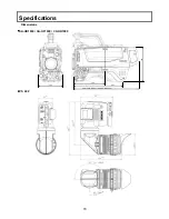
Page 84: ...70 Specifications Dimensions SK HD1800 CA HF1000 CX HD1000 VF 402 133 166 262 348 CA HF1000 360 CX HD1000 191 ...

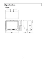
Page 85: ...71 Specifications VF L90HD ...

Page 86: ...0 Viewfinder adaptor AT S951 Lens Mountor LM B1000 Lens Mountor LM P1000 Microphone adaptor MH 1000 9inch View finder VF L9HD VF L90HD VF Adaptor AT 90 Setup control unit SU 1000 Tripodd adaptor TA Z3 Portable Zoom Lens Studio Adaptor SA 1000 Large Box Lens Small Box Lens Remote Control Cable VF Adaptor AT 951 Lens Mountor LM C1000 for Canon LM F1000 for Fujion Portable Zoom Lens Triax Adaptor CX ...

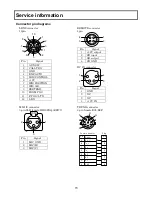
Page 87: ... 12 L RX REMOTE connector 4pin 1 2 3 4 Pin Signal 1 12V output 2 SD input 3 SD output 4 SD GND DC IN connector 1 2 3 4 Pin Signal 1 GND 2 NC 3 NC 4 12V IN MIC1 2 connector 3 pin XLR female HR16PRQ 3SE 71 PUSH 1 2 3 Pin Signal 1 MIC GND 2 MIC H 3 MIC C TRUNK connector 8 pin female R05 R8F A G B F C E D H P in A B C D S ig n a l T x_ R x_ R x_ T x_ C a m e ra A d a p to r E F G H N C N C N C G N D P...

Page 88: ... NC 5 RET 1 CTL 6 RET 2 CTL SCRIPT 5 pin female HR10A 7R 5SB 73 Mating connector HR10A 7P 5P 2 1 3 4 5 Pin Signal 1 SCRIPT 12V 2 GND 3 NC 4 NC 5 NC AC230 V OUT 5 pin female RM12BRB 5S Mating connector RM12BPE 5PH 5 4 1 2 3 Pin Signal 1 AC 230V 2 AC 0V 3 GND 4 TALLY OUT 5 AC CTL Open collector CAUTION Do not connect the FS F5 cable during the Camera system power on It is AC230V output connector FS ...

Page 89: ...k Pin 5 to Pin 3 Please ensure all local and national Electrical Safety regulations are complied with when connecting these power lines Notes If an over current fault is detected on the AC Power line the Protective circuit in the CCU will shut down power to the Camera Adaptor and Camera head Please avoid switching AC control line during live recording due to possible interference to the Video sign...

Page 90: ...dio Adaptor SA 1000 Large Box Lens Small Box Lens Lens Mountor LM C1000 for Canon LM F1000 for Fujion Portable Zoom Lens Notes Supply power to a studio box lens from an external power supply unit which can connect with a lens directly when not using the SA 1000 but using a lens supporter provided by the lens manufacture Refer to an operation manual of a lens and a lens supporter for details ...

Reviews: