


Maintenance
Technical Catalogue
TCGB0051 rev 0 - 09/2009
70
4. Waste Fluid
- Stop the acid-resistant pump.
- Put the waste fluid into the waste fluid tank.
- Supply water into the cleaning tank and operate the pump for water cleaning.
- Put the cleaning water into the waste fluid tank as same as the waste fluid.
- Measure pH degree by using a pH test sheet and neutralize the waste fluid by gradually adding neutralizing
agent.
- After neutralization ask a waste fluid treatment contractors to handle it.
5. Neutralisation Treatment in the Water Piping
- Put water into the cleaning tank.
- Operate the acid-resistant pump after air-purging.
- Measure the pH degree and gradually add neutralizing agent until the pH reaches pH = 7.
- Operate the pump for a specified period of time for neutralization.
- Discharge the used water.
- Operate the circulating pump and clean the circuit with water until no fouling fluid is observed.
6. Re-starting
- Reconnect the water piping as they were so that the water Chiller can operate.
- After cleaning, perform water treatment (preventive treatment) in order to prevent the water circuit from
corrosion.
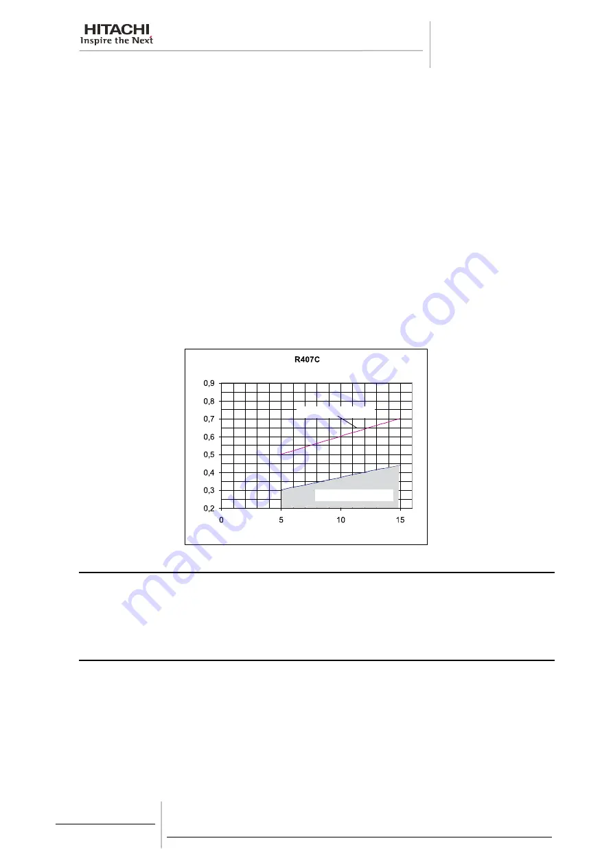
Suction Gas Pressure (MPa)
Chilled Water Outlet Temperature (ºC)
Saturation Line
Area Requiring Cleaning
11.5. Winter shutdown
When shutting down the unit for winter, clean the inside and outside of the cabinet, and dry the unit. Pump down the
refrigerant to the condenser and close the liquid outlet stop valves. This unit should be covered during shutdown, in order
to protect it from dust and environmental conditions. Be sure to tighten the packing glands and the cap nuts of the valves.
Remove the drain plug and drain all residual water from the condenser and water cooler piping systems, as such water
may freeze during the cold season. It is very helpful to supply brine (anti-freezer) to the piping systems.
11.6. Spring start-up
After any extended shutdown period, prepare the unit for operation as follows.
1. Thoroughly inspect and clean the unit.
2. Clean the water piping lines and the strainer.
3. Inspect the pump, the cooling tower and/or regulating valve.
4. Tighten all wiring connections and access panel
CAUTION:
When the main switch for this unit has been at the OFF position for an extended period of time, it should be switched ON at least
12 hours before start-up, so that oil in the compressor discharge casing may be warmed enough, to prevent oil foaming by the oil
heater during start-up.
Summary of Contents for SAMURAI CLG2
Page 2: ......
Page 4: ......
Page 6: ......
Page 10: ......
Page 12: ......
Page 46: ......
Page 62: ......
Page 66: ......
Page 82: ......
Page 94: ...Drawings Technical Catalogue TCGB0051 rev 0 09 2009 94 14 2 4 Main printed circuit board ...
Page 95: ...Drawings Technical Catalogue 14 95 TCGB0051 rev 0 09 2009 14 2 5 Relays printed circuit board ...
Page 98: ......
Page 112: ......
Page 116: ......
Page 117: ......