background image

Application Data

Technical Catalogue

16

109

TCGB0051 rev 0 - 09/2009


¡

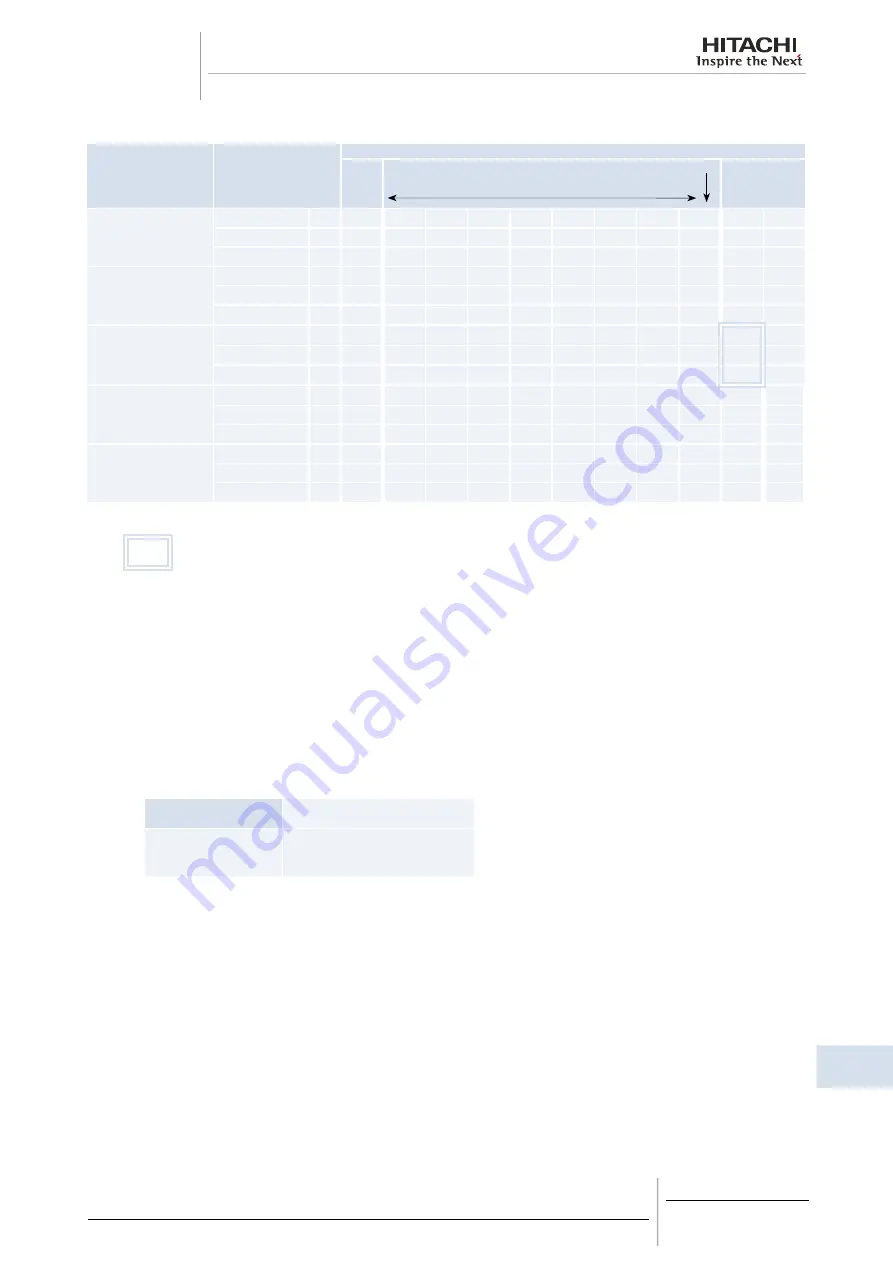
Model: RCUE80CLG2, RCUE100CLG2 and RCUE120CLG2

Condensing

Temperature

Performance

Compressor Load

7.5* 

%

15~99%

Full

55°C

Capacity

%

10

20

30

40

50

60

70

80

90

92

Input

%

22

43

52

59

68

77

89

103

119

123

EER

%

47

47

58

68

74

78

79

78

76

75

50°C

Capacity

%

10

20

30

40

50

60

70

80

90

96

Input

%

19

37

46

53

60

68

77

88

104

112

EER

%

54

54

65

75

83

88

91

91

87

86

45°C

Capacity

%

10

20

30

40

50

60

70

80

90

100

Input

%

17

33

39

46

53

59

66

76

87

100

EER

%

61

61

77

87

94

102

106

105

103

100

40°C

Capacity

%

10

20

30

40

50

60

70

80

90

100

104

Input

%

14

28

35

40

45

51

58

66

73

85

89

EER

%

71

71

86

100

111

118

121

121

123

118

117

35°C

Capacity

%

11

21

30

40

50

60

70

80

90

100

109

Input

%

13

25

30

34

39

44

51

54

62

70

78

EER

%

84

84

100

118

128

136

137

148

145

143

140

:Standard Condition 

(Condensing temperature: 45°C)  

(Cooler Water Inlet/Outlet: 12/7°C)

 NOTE:

1.    Capacity: Cooling Capacity (kW)
  Input: Compressor Input Power (kW)
  EER: Capacity/Input (kW/kW)
2.  Operating Conditions:
  Chilled Water Outlet Temperature: 7°C
  Water Flow Rate: Constant
3.  Above Table shows the percentage of Capacity, input and EER based on the standard condition.

Therefore, each value can be calculated as below example:

Example: Model RCUE100 CLG2

Standard Condition

Condensing Temperature 40 °C, 

Capacity 80%

Capacity:

290 kW

Capacity:

 290 × 0.8 = 232 kW

Input:

84.8 kW

Input:

84.8 × 0.66 = 56.0 kW

EER:

3.42

EER:

3.42 × 1.21 = 4.14

4.  Control marked (*) is available by the optional selection switch DSW7-3 / ON: Minimum Load Extension.

Summary of Contents for SAMURAI CLG2

Page 1: ...tion operation and maintenance instructions Design information RCUE40CLG2 RCUE50CLG2 RCUE60CLG2 RCUE80CLG2 RCUE100CLG2 RCUE120CLG2 Technical Catalogue SAMURAI SERIES CONDENSERLESS WATER CHILLERS SCREW TYPE CLG2 ...

Page 2: ......

Page 3: ...hout notice in order that HITACHI may bring the latest innovations to their customers Whilst every effort is made to ensure that all specifications are correct printing errors are beyond Hitachi s control Hitachi cannot be held responsible for these errors ...

Page 4: ......

Page 5: ...Instructions Components of chiller Preparation Initial Check Installation Test Running Controller Adjustment Self Inspection Functions Control System Maintenance Troubleshooting General Specifications Drawings Model Selection Application Data Components Data 1 2 3 4 5 6 7 8 9 10 11 12 13 14 15 16 17 ...

Page 6: ......

Page 7: ...3 Centre of gravity 26 5 4 Service space and foundation 27 5 5 Transportation by rigging 28 6 Installation 29 6 1 Electrical Wiring 30 6 2 Water Piping 32 6 3 Minimum internal system water volume 33 6 4 Water control 34 6 5 Refrigerant piping 34 6 6 BMS connection 37 6 7 CSC 5S 44 6 8 Installation final check 45 7 Test running 47 7 1 Preparation 48 7 2 Test running procedure 48 7 3 Instructions af...

Page 8: ...20 CLG2 72 11 10 Compressor removal 73 11 11 Safety and protection control 73 11 12 Normal operating pressure 75 11 13 Test running and maintenance record 76 11 14 Daily operating records 77 11 15 Servicing for R407C refrigerant system 78 12 Troubleshooting 79 12 1 Troubleshooting table 80 13 General specifications 83 13 1 General data 84 13 2 Option line up 86 14 Drawings 87 14 1 Dimensional Draw...

Page 9: ...e your condenserless type its abbreviation and reference number in this technical catalogue CLG2 SERIES Unit Code Unit Code RCUE40CLG2 8E042072 RCUE80CLG2 8E082072 RCUE50CLG2 8E052072 RCUE100CLG2 8E102072 RCUE60CLG2 8E062072 RCUE120CLG2 8E122072 3 RCUE60CLG2 Unit type Capacity HP Series R407C refrigerant Condenserless ...

Page 10: ......

Page 11: ...ARNING Hazards or unsafe practices which COULD result in severe personal injury or death CAUTION Hazards or unsafe practices which COULD result in minor personal injury or product or property damage NOTE Useful information for operation and or maintenance If you have any questions contact your contractor or dealer of HITACHI This instruction gives a common description and information for this cond...

Page 12: ......

Page 13: ...cal Catalogue 2 2 F e a t u r e s a n d B e n e f i t s 13 TCGB0051 rev 0 09 2009 Contents 2 Features and benefits 13 2 1 Chiller picture 14 2 2 Compressor 14 2 3 Control 16 2 4 Heat Exchanger 17 2 5 Electronic Expansion Valve 18 ...

Page 14: ...ers a screw type Condenser less Chillers A range of capacity are available from 120 kW to 360 kW 2 2 Compressor THE SAMURAI RANGE INCORPORATES THE LATEST DEVELOPMENT OF HITACHI S SCREW COMPRESSOR TECHNOLOGY FOR THE NEW MILLENNIUM Highly Reliable HITACHI Two Pole Motor Built in Oil Separator Cyclone oil separator Oil Sight Glass Oil Heater High precision Twin Screw Rotors Suction Filter ...

Page 15: ...m Time second PRINCIPLE OF COMPRESSION CONTINUOUS CAPACITY CONTROL HITACHI s Continuous Capacity Control system uses advanced electronic controls to position the infinitely variable slide valve within each compressor This modulation allows exact load control and accurate chilled water temperature without the need for expensive inverters COOLING LOAD Cooling load continuos capacity control Step con...

Page 16: ...ly matched Continuous Capacity Control takes advantage of high efficiency part load performance Frequent compressor starts and stops are eliminated PART LOAD PERFORMANCE 2 3 Control Many Functions Newly developed Control Board has many functions shown below as standard Forced compressor load control 2 different temperature setting Memory for data in alarm Automatic restart after power failure MOTO...

Page 17: ...0 5ºC Load Up 2 Load Up 1 Quick cooling Outlet Water Temperature WATER TEMPERATURE Start CONVENTIONAL STEP CONTROL WATER TEMPERATURE Restart OutletTemperature 1st step Final step Temperature Band 7ºC normally 2 4 Heat Exchanger Plate Type Heat Exchanger The new Condenser less Chillers are equipped with plate type Heat Exchangers which have many advantages when compared with conventional Shell Tube...

Page 18: ...18 2 5 Electronic Expansion Valve This unit are equipped with an electronic expansion valve to provide sophisticated control under any temperature condition The electronic expansion valve provides reduced electrical power consumption compared to the classical system ...

Page 19: ...n Instructions Technical Catalogue 3 3 O p e r a t i o n I n s t r u c t i o n s 19 TCGB0051 rev 0 09 2009 Contents 3 Operation instructions 19 3 1 HITACHI condenserless Water Chiller Models RCUE 40 120 CLG2 20 ...

Page 20: ...witch Field Supplied 2 Switch OFF the main power source when the unit is shut down for a long period of time Pilot Lamp The red LED indicates the normal operation When the orange LED is activated any one of the safety devices may be functioning Please contact your service shop if this condition is detected Daily Checking 1 Check the power supply to ensure that it is proper 2 Check for abnormal sou...

Page 21: ...Components of Chiller Technical Catalogue 4 4 C o m p o n e n t s o f C h i l l e r 21 TCGB0051 rev 0 09 2009 Contents 4 Components of chiller 21 4 1 Structure drawing 22 ...

Page 22: ...URE DRAWING OF HITACHI CONDENSER LESS WATER CHILLER UNIT Example RCUE60CLG2 N Name Compressor Water Cooler Electrical Box Power Wiring Supply Check Valve Oil Sight Glass Operation Switch Electronic Expansion Valve Liquid Line Stop Valve Drier Liquid Sight Glass Solenoid Valve High Pressure Switch Pressure Relief Valve Remote Local changeover Switch is at rear side ...

Page 23: ...ev 0 09 2009 Contents 5 Preparation initial check 23 5 1 Initial check 24 5 2 Placing the unit 25 5 3 Centre of gravity 26 5 4 Service space and foundation 27 5 5 Transportation by rigging 28 5 5 1 Transportation by rigging 28 5 5 2 Transportation by roller 28 5 5 3 Declining the unit during transportation 28 ...

Page 24: ... work in the space specified in Fig 1 Foundation Check to ensure that the foundation is flat level and sufficiently strong taking into account the maximum foundation gradient Fig 2 and the unit weight balance Confirm elevation provision for the unit on a solid base with an iron frame or concrete curbs shown in chap 5 4 In order to obtain proper clearance beneath the unit for on the ground installa...

Page 25: ...t install the unit outdoors If installed outdoor an electrical leakage will occur since the unit has not been designed for dew protection If leakage is detected stop the unit and contact the installer or a service shop Do not use a naked fire near the refrigerant gas If a naked fire is utilised near the refrigerant gas refrigerant is turned into a harmful phosgene compound WARNING This unit is ope...

Page 26: ...vity 1 2 B A 3 4 Model RCUE CLG2 40 50 60 80 100 120 Location Weight Distribution kg 1 190 205 225 350 405 425 2 120 130 135 290 325 335 3 210 230 250 335 355 385 4 130 145 150 275 285 305 Operating Weight kg 650 710 760 1250 1370 1450 Location of Centre of Gravity mm Dimension A 420 415 415 535 555 550 Dimension B 565 570 575 895 905 910 ...

Page 27: ...il of foundation example RCUE60CLG2 Nº Name Nº Name 1 4 Ø 26 Mounting Holes 8 Steel Plate 1 mm 2 Electrical Box 9 Concrete 3 Bottom Frame 10 Vibration proof Rubber Mat 1 mat per position option 4 Vibration proof Rubber Mat 4 positions 11 Washer 5 Vibration proof Rubber Mat 8 positions 12 Nut 6 Foundation bolt M20 13 Bottom Frame 7 Rubber Bush option ...

Page 28: ...cated on the unit label Lifting drawing of Hitachi condenser less water chiller unit Example RCUE60CLG2 N Name 60º or more Electrical Box 4 x Rigging Holes Spreader Bar Field supplied Lifting Bracket Field supplied 5 5 2 Transportation by roller When rolling the unit put at least 6 equal sized rollers under the base frames Each roller must carry both the outer frames and must be suited to balance ...

Page 29: ... Piping Connection 34 6 5 2 Evacuation and Refrigerant charge 37 6 6 BMS connection 37 6 6 1 System 37 6 6 2 Signal 38 6 6 3 Caution on use HARC70 CE1 op 38 6 6 4 Dimensional drawing and Specifications of Hitachi gateway model HARC70 CE1 HARC70 CE1 0P 39 6 7 CSC 5S 44 6 7 1 System 44 6 7 2 Signal 44 6 7 3 Caution on use of CSC 5S 45 6 7 4 Transmitting setting on chiller control PCB 45 6 8 Installa...

Page 30: ...ing supplied to the installation location prior to any electrical installation work 1 Install the field supplied main switch box es at a properly selected location 2 Install conduit connectors in the hole for the power wiring 3 Lead main power wires and the earthing wire through the connector to the screw terminals for main power and earthing in the magnetic switch box The neutral wires for 380V 5...

Page 31: ... Thermostat Operation 14 Only used for Diff Water Pressure switch OPTION Flow Switch OPTION 15 Force Compressor Load Operation 16 Free Cooling Output signal Only cycle Nº 1 17 In case of individual indication without Remote Control Switch 18 Customer wiring 19 Force compressor load 20 Setting of low voltage control NOTE 1 All the settings shall be performed before Power ON 2 Remote Local Change ov...

Page 32: ...ool and to prevent sweating of the piping 7 Under the condition where the ambient temperature is low in winter there is a case where equipment and piping will become damaged during the shutdown periods at night because the water in the pump or piping will be frozen To prevent freezing of the water it is effective to operate the pumps even during shutdown period HITACHI Chiller has the pump ON OFF ...

Page 33: ... without interruption the internal chilled water volume in the piping system should be greater than the minimum volume as shown below NOTE Minimum internal system water volume written above is for standard ON OFF differential minimum internal system water volume shall be increased by the setting of differential Model RCUE CLG2 40 50 60 80 100 120 Chilled Water Flow Range Min m3 h 15 5 18 7 23 2 31...

Page 34: ...s than 50 Less than 50 Sulphur Acid Ion mg SO4 2 I Less than 50 Less than 50 The Amount of Acid Consumption pH 4 8 mg CaCO3 I Less than 50 Less than 50 Total Hardness mg CaCO3 I Less than 70 Less than 70 Calcium Hardness mg CaCO3 I Less than 50 Less than 50 Silica L mg SIO2 I Less than 30 Less than 30 Reference Quality Total Iron mg Fe I Less than 1 0 Less than 0 3 Total Copper mg Cu I Less than 1...

Page 35: ...in wich the piping accessories are included by soldering brazing or flare connections The oil trap and liquid loop should be situated at the position as shown in figure 3 These chiller units are equipped with an unloader system In this system the pipe diameter of the discharge piping must be selected so that sufficient oil will be carried even during minimum unloader operation For this reason an e...

Page 36: ...ser Remote Condenser Oil Trap Oil Trap Oil Trap Oil Trap At each 10 meters At each 10 meters Receiver Receiver Chiller Unit Maximum 25 meters Example of Double Riser Field Supplied Remote Condenser Oil Trap Oil Trap Chiller Unit At each 10 meters Water chiller is above the remote condenser Chiller Unit Maximum 5 meters Field Supplied Receiver Receiver Remote Condenser Remote Condenser ...

Page 37: ...cuum pump with the refrigerant cylinder placed on the weighing scales 1 Purge air from the cylinder connection line 2 Charge liquid refrigerant R 407C into the refrigeration cycle by weighing the refrigerant cylinder 3 Remove the charging hose 4 After all evacuation and charging work tighten the packing gland and the cap nuts of the unit stop valves NOTE 1 A gauge manifold or equivalent piping con...

Page 38: ...nsmitting occurs between HARC and Chiller unit and Chiller unit stops in the case of operation starting by Monitoring Device then transmit an operation order after you transmit a stop order once If it isn t carried out it can t start 6 After Chiller unit under control by HARC is stopped by the control panel and operation is done from the Monitoring Device then transmit an operation order after you...

Page 39: ...rature and mode continue maintaining the initialisation value by Chiller unit 13 When the abnormal transmitting occurs between the Monitoring Device and HARC then the condition of the Monitoring Device may not correspond with the condition of HARC Set MaxSendTime and try that the condition of the Monitoring Device corresponds with the condition of HARC in the interval of MaxSendTime 14 It can t be...

Page 40: ...en LonWorks Signal Wire DC 5V Field Supplied Marking of Terminals POW CONTROLSYSTEM G W HITACHI MCLR LON SERV AC AC E LON H LINK S201 S202 LON H LINK PAC IRP Mark Indication POW Red Power Supply AC220 240V IRP Green Lighted During Transmission Between LONWORKS PAC Yellow Lighted During Transmission Between Chiller Wiring Procedures Section Wiring Method Remark Power Line 1φ220 240V Power Source HA...

Page 41: ... O O O nv22 nvoLvgCHWTemp_1 SNVT_temp_p 105 Chilled outlet temperature Same than nv7 1 O O O O nv23 nvoEntCHWTemp_1 SNVT_temp_p 105 Chilled inlet temperature Same than nv8 1 O O O O nv24 nvoAlarmDescr_1 SNVT_str_asc 36 Alarm code Same than nv9 1 O O O O nv25 nvoChillerStat_1 SNVT_chlr_status 127 Chiller Status Same than nv10 1 nv26 untest_4 SNVT_press Not Available 30 NOT USED NOT USED Not used 1 ...

Page 42: ...T_press 30 Suction Pressure 6 2 Bytes 0 30000 0 3 000 kPa O O O O n23 nvoDtemp1 SNVT_temp_p 105 Discharge Temp 1 2 Bytes 12700 12700 127 127 ºC O O O O n24 nvoDtemp2 SNVT_temp_p 105 Discharge Temp 2 2 Bytes 12700 12700 127 127 ºC O O n25 nvoDtemp3 SNVT_temp_p 105 Discharge Temp 3 2 Bytes 12700 12700 127 127 ºC O O n26 nvoDtemp4 SNVT_temp_p 105 Discharge Temp 4 2 Bytes 12700 12700 127 127 ºC O n27 ...

Page 43: ...lative Humidity 0 45 C 10 80 with condition of no condensation Net weight 0 6kg Colour Grey Munsell 5Y7 1 or similar Material of Box ABS resin molding material Mounting Method Wall Mount By 2 x M4 Screws or on DIN Rail 35mm Mounting Location In Weather and Dust Proofed Control Panel Accessories Core x 1 Capacitor x 1 Transceiver Using FTT 10A Warranty No warranty shall be applied for the control a...

Page 44: ...ssure MPa Indicate Max 6 Refrigerant Circuit Data Monitoring Data C1Ps C2Ps Suction Pressure MPa C1td C2td Discharge Gas Temperature C C1ts C2ts Suction Gas Temperature C C1tr C2tr Liquid Refrigerant Temperature C CEL Inlet Water Temperature C CoL Outlet Water Temperature C CcoL Individual Water Piping Outlet Temperature C The display contents depend on chiller unit tSC Setting Temperature of Chil...

Page 45: ...cording to all documents and drawings Sub chapter 6 8 1 shows the minimum check points 6 8 1 Installation work check list 1 Is the unit solidly mounted and levelled 2 Is the installation location adequate Indoor Installation Space for Maintenance Work Noise and Vibration Sunshine and other Heat Sources Appearance 3 Is the water piping system adequate Tube Size Water Drain Length Water Control Flex...

Page 46: ......

Page 47: ...Test Running Technical Catalogue 7 7 Te s t R u n n i n g 47 TCGB0051 rev 0 09 2009 Contents 7 Test running 47 7 1 Preparation 48 7 2 Test running procedure 48 7 3 Instructions after test running 48 ...

Page 48: ...l phase protection device Cut the main switch and interchange two of three terminals R S and T on the main terminals at the field connection side in the unit 1 Operate the pump for chilled water and other auxiliary equipment such as fan coil units and air handling units Check to ensure that the chilled water flows sufficiently and that other auxiliary equipment operate properly 2 Set the switch at...

Page 49: ...er Adjustment Technical Catalogue 8 8 C o n t r o l l e r A d j u s t m e n t 49 TCGB0051 rev 0 09 2009 Contents 8 Controller adjustment 49 8 1 PCB Drawing 50 8 2 Control System 51 8 3 Controller Adjustment 51 ...

Page 50: ...op Fan Selection NOT AVAILABLE Mode Set Switch A DEPEND ON MODEL Manual Defrost Heat Pump NOT AVAILABLE Optional Function B STANDARD ALL OFF Optional Function C STANDARD ALL OFF Mode Set Switch B Local Remote Changeover Switch STANDARD Local Cool Heat Changeover Switch STANDARD Cool Current Limitation Not Available Neutral Zone Setting STANDARD 3 Hot Water Temperature Setting for Heat Pump NOT AVA...

Page 51: ...of the screw compressor cycling protection ccp connected in the compressor control circuit delays the screw compressor restarting period for approximately three 3 minutes for No 1 compressor four 4 minutes for No 2 compressor Electronic Thermostat Circuit The electronic thermostat senses chilled water outlet temperature and operate capacity control solenoid valves of HITACHI screw compressor Screw...

Page 52: ...ode Set by DSW5 5 pin Set by DSW5 3 4 pin 9 C 7 C 6 C Water Outlet Temperature Water Inlet Temperature Set by RSW8 Set by DSW5 1 2 pin Neutral Zone Setting Temperature Inlet Water Temp when system is stopped with Thermo Off mode Load Down Mode Thermo Off Standard Setting Continuous Capacity Control Setting Switch DSW5 Temperature Band for Stop Setting Switch 1 degree is standard The figure 1 and 2...

Page 53: ...gnal Time for Load up 2 and Load down Mode Setting Switch 2 seconds is standard The figure 7 and 8 of the DSW5 switch are already set at figure 7 ON side 8 ON side The locations at the figure 7 and 8 of the DSW5 mean as follows Figure 7 8 7 8 7 8 7 8 Location ON ON ON OFF OFF ON OFF OFF Time second 2 4 6 8 Interval of Output Signal Time for Load up 2 and Load down Mode Setting Switch 60 seconds is...

Page 54: ... are for compressor size setting as follows Figure 9 10 9 10 9 10 Location OFF ON ON OFF ON ON Compressor 40 HP 50 HP 60 HP Selection Switch for Cooling Heating Operation SW8 All model in this series are for cooling only So that Heating function is Not available The SW8 Selection Switch must be turned to the upper side Selection Switch for Local Remote Operation SW6 Local operation is standard So ...

Page 55: ...ical Catalogue 9 9 S e l f I n s p e c t i o n f u n c t i o n s 55 TCGB0051 rev 0 09 2009 Contents 9 Self Inspection functions 55 9 1 Alarm Indication 56 9 2 Normal Indication 57 9 3 Function for indication of operation condition 57 ...

Page 56: ...n Short Failure of Discharge Gas Thermistor Open Short Failure of Thermistor set before Expansion Valve Failure of Water Outlet Thermistor Rear side of Water Cooler Failure of Suction Gas Thermistor Open Short Failure of Discharge Gas Pressure Sensor Open Short Failure of Suction Gas Pressure Sensor Open Short Phase Abnormally Failure of Water Inlet Temperature Thermistor Failure of Water Outlet T...

Page 57: ...tting differential temperature and the last alarm code are digitally indicated on the control panel The Alarm Code Occurrence Data Normal Operation Condition 88 Co oF Checking Indication Memory Data Indication in Alarm Latest Data only Second Water Temperature Setting NOTE Each indication mode shall be changed from the normal mode Press the check and switches simultaneously for more than 3 sec It ...

Page 58: ...nder this indication mode this indication mode is changed to the alarm indication mode Checking Indication Back to CPU ROM number Last Alarm Code Occurred no alarm Discharge Pressure MPa N 1 Cycle 1 92 MPa Discharge Pressure MPa Suction Pressure MPa N 1 Cycle 0 42 MPa Suction Pressure MPa Discharge Gas Temperature Option C N 1 Cycle 82 C Discharge Gas Temperature Option C Suction Gas Temperature C...

Page 59: ... Difference C Compressor Capacity Control C Load up Compressor Capacity Control C Hold Thermo off Control Status Compressor start control Control Status Suction pressure control activated Discharge Pressure Control High Efficiency Mode Suction Pressure Control Low Noise Mode Different Pressure Control Load Down Control Water Outlet Temp Freeze Protection Control Not Available Compressor Start Cont...

Page 60: ...mperature It can be changed by external signal Second Water Temperature Setting Procedure 1 Press the check switch for more than 3 seconds Then display shows the current setting value This shows the setting value is 6ºC If press the check or in this mode the display is changed to either Hot Water Temperature Setting or Chilled Water Temperature Setting alternatively 2 Press the check and switches ...

Page 61: ...sly for more than 3 seconds At the same time the setting value shown on display is memorized and available The setting is changed to 9 5ºC Hot water temperature setting change is performed by same procedure mention above When the wiring connection shown below this second temperature setting is available Available Not ...

Page 62: ......

Page 63: ...10 C o n t r o l S y s t e m 63 TCGB0051 rev 0 09 2009 Contents 10 Control system 63 10 1 Standard operating sequence for RCUE40CLG2 RCUE50CLG2 and RCUE60CLG2 64 10 2 Standard operating sequence for RCUE80CLG2 RCUE100CLG2 and RCUE120CLG2 65 ...

Page 64: ...icator OFF ON ON ON ON ON ON ON ON ON ON ON ON ON ON ON ON ON OFF Operation Indicator OFF OFF OFF ON ON ON ON ON ON ON ON ON ON ON ON OFF ON OFF OFF Alarm Indicator OFF OFF OFF OFF OFF OFF OFF OFF OFF OFF OFF OFF OFF OFF ON OFF OFF OFF OFF Oil Heater CH1 OFF ON ON ON OFF OFF OFF OFF OFF OFF OFF OFF ON OFF ON ON ON ON OFF Compressor Motor STA DLT DLT DLT DLT DLT DLT DLT DLT DLT MC1 OFF OFF OFF OFF ...

Page 65: ... ON OFF OFF OFF OFF OFF OFF OFF OFF OFF OFF ON OFF ON ON ON ON ON OFF CH2 OFF ON ON ON ON ON OFF OFF OFF OFF OFF OFF OFF OFF ON OFF OFF ON ON ON ON OFF Compressor Motor STA DLT STA DLT DLT DLT DLT DLT DLT DLT DLT DLT MC1 OFF OFF OFF OFF ULD ULD ULD ULD ULD FLD FLD ULD ULD ULD OFF ULD OFF OFF OFF FLD OFF OFF 15 15 15 15 15 99 100 100 15 99 15 99 15 15 99 100 STA DLT DLT DLT DLT DLT DLT DLT DLT DLT ...

Page 66: ......

Page 67: ...art up 70 11 7 Part replacement 71 11 8 Refrigeration cycle 71 11 9 Refrigerant cycle diagram of Hitachi condenserless Chiller RCUE 40 50 60 80 100 120 CLG2 72 11 10 Compressor removal 73 11 11 Safety and protection control 73 11 11 1 Safety and control device setting 74 11 12 Normal operating pressure 75 11 13 Test running and maintenance record 76 11 14 Daily operating records 77 11 15 Servicing...

Page 68: ...ically according to its clogging degree If not cleaned periodically the water strainer will be broken due to an excessive pressure to the strainer screen WARNING This product is equipped with plate type heat exchangers In the plate type heat exchanger water flows through a narrow space between plates Therefore there is a possibility that freezing may occur if foreign particles or dusts are clogged...

Page 69: ...ection shoes protection cloth protection mask etc in order not to absorb or touch these agents during this cleaning work 11 4 Cleaning method 1 2 6 4 3 4 5 8 7 N Name N Name 1 Chiller Unit 5 Diluted Cleaning Fluid 2 Chilled Water Inlet Piping 6 Chilled Water Outlet Piping 3 Acid resistant Type Water Pump 7 Cleaning Water Tank 4 Hose 8 Waste Fluid Tank 1 Installation of Cleaning Circuit Stop the wa...

Page 70: ...rosion Suction Gas Pressure MPa Chilled Water Outlet Temperature ºC Saturation Line Area Requiring Cleaning 11 5 Winter shutdown When shutting down the unit for winter clean the inside and outside of the cabinet and dry the unit Pump down the refrigerant to the condenser and close the liquid outlet stop valves This unit should be covered during shutdown in order to protect it from dust and environ...

Page 71: ...ng preparation shown below is recommended as a convenient procedure regarding both charging and evacuation Fully open all the stop valves Connect the evacuation line to the check joints of the high and the low pressure sides Completely evacuate the entire cycle with a vacuum pump Charge refrigerant to the refrigeration cycle by weighing the charging cylinder The proper refrigerant charge is listed...

Page 72: ...sure Relief Valve Field supplied 17 Pressure Sensor High 6 Remote Condenser Field supplied 18 Compressor Safety Valve Option 7 Stop Valve 19 Compressor Dual Safety Valve Option 8 Stop Valve A High Pressure Gauge 9 Drier B Low Pressure Gauge 10 Solenoid Valve C Stop Valve 11 Sight Glass D Charging Cylinder 12 Electronic Expansion Valve E Vacuum Pump NOTE R407C shall be charged by LIQUID Condenserle...

Page 73: ...the water Chiller for 10 minutes and check to ensure that the oil level is maintained at a stable condition 4 Stop the Chiller and completely close the liquid stop valve 5 Operate the Chiller after circulating water through the water cooler and field supplied condenser 6 Stop the Chiller when the low pressure reaches at approximately 0 05 MPa Do not operate at the pressure lower than 0 05 MPa If o...

Page 74: ...se A 125 125 160 125 125 160 Manual reset adjustable one three phase set for each compressor motor Thermal Relay A 54 65 80 54 65 80 Manual reset adjustable one three phase set for each compressor motor Magnetic Circuit Protector Option A 90 107 135 90 107 135 Oil Heater One heater for each compressor motor Capacity W 150 150 150 150 150 150 Discharge Gas Electronic Control One for each cycle Cut ...

Page 75: ...mes higher than 100 C Use Do not utilize this unit for cooling of drinking water or food Comply with local codes and regulations Failure Turn OFF all the main switches if refrigerant leakage or chilled water leakage occurs Also if the unit can not be stopped by the control switch turn OFF all the switches for power source Activation of Safety Device In the case that one of safety devices is activa...

Page 76: ...led been lubricated 4 Has the unit been operated for at least twenty minutes 5 Check Chilled Water Temperature Inlet ºC Outlet ºC 6 Check Condenser Water Temperature Water Cooled Type Inlet ºC Outlet ºC 7 Check Condenser Air Inlet Temperature Air Cooled Type Inlet ºC Outlet ºC 8 Check Suction Line Temperature and Superheat Suction Line Temperature ºC ºC Superheat ºC ºC 9 Check Pressure Discharge P...

Page 77: ... ºC Compressor High Pressure MPa Low Pressure MPa Voltage V Current A Condenser Water Temperature Water Cooled Type Condenser Air Temperature Air Cooled Type Inlet ºC Outlet ºC Chilled Water Temperature Inlet ºC Outlet ºC Current for Condenser Water Pump In the case of Water Cooled Type A Current for Chilled Water Pump A Current for Cooling Tower In the case of Water Cooled Type A NOTES ...

Page 78: ...into the system and the difficult vaporising one would be remained in the charge cylinder The cylinder gauge equipped manifold and charge hose are only used for R407C refrigerant Adjust the cylinder setting to charge in liquid Refrigeration Oil Japan Energy Freol UX300 which R407C refrigerant is easy to blend into it is used for this system The other oil is prohibited to use so that not to be mixe...

Page 79: ...Troubleshooting Technical Catalogue 12 12 Tr o u b l e s h o o t i n g 79 TCGB0051 rev 0 09 2009 Contents 12 Troubleshooting 79 12 1 Troubleshooting table 80 ...

Page 80: ...tage Single Phase or Phase Imbalance 1 Check the power supply line and contactors Repair if necessary Excessive Superheat 1 Check for refrigerant leakage Defective Element 1 Check the contact of the internal thermostat during the cold condition Excessive High Discharge Pressure and Low Suction Pressure 1 See High Discharge Pressure and High Suction Pressure Insufficient Cooling High Discharge Pres...

Page 81: ...charge Pressure Refrigerant Overcharged 1 Purge the refrigerant Liquid Refrigerant Flooding Back from the Water Cooler 1 Check the operation and adjustment of the expansion valve Be sure that the feeler bulb is tightly connected to the suction pipe and completely insulated 2 Inlet chilled water temperature to the unit is considerably higher than the standard temperature Leakage from the Condenser ...

Page 82: ......

Page 83: ...General Specifications Technical Catalogue 13 13 G e n e r a l S p e c i f i c a t i o n s 83 TCGB0051 rev 0 09 2009 Contents 13 General specifications 83 13 1 General data 84 13 2 Option line up 86 ...

Page 84: ...aporator type Brazing plate type Control system Micro Processor Piping connections Evaporator water piping 3 Victaulic 1xINLET 1xOUTLET Refrigerant gas piping mm 41 3 Outer Diameter Refrigerant liquid piping mm 28 6 Outer Diameter Chilled water outlet temperature ºC 5 15 Condensing temp Tc ºC 30 65 Permissible water pressure of evaporator MPa 1 03 Safety and protection devices Reverse Phase Protec...

Page 85: ...ype Brazing Plate Type Control system Micro Processor Piping connections Evaporator water piping inch 3 Victaulic 1 x INLET 1 x OUTLET Refrigerant gas piping mm 41 3 Outer Diameter x 2 Refrigerant liquid piping mm 28 6 Outer Diameter x 2 Chilled water outlet temperature ºC 5 15 Condensing temperature tc ºC 30 65 Permissible water pressure of evaporator Mpa 1 03 Safety and protection devices Revers...

Page 86: ...on Alarm DC24V External Control Level or pulse Short Period Power OFF Protection Power Failure Recover Control 2 Different Temperature Setting Remote Control Switch AC 220 240V BMS Control HARC 70CE1 OP LON WORKS CSC 5S Number Cable Refrigeration Cycle Independent Circuit Insulation Suction Pipe Low pressure side Discharge Valve Suction Valve Dual Safety Valve Suction Safety Valve Compressor Safet...

Page 87: ... 14 1 4 RCUE80CLG2 89 14 1 5 RCUE100CLG2 90 14 1 6 RCUE120CLG2 90 14 2 Wiring Diagrams 91 14 2 1 Power circuit for RCUE 40 120 CLG2 91 14 2 2 Control circuit for RCUE40CLG2 RCUE50CLG2 and RCUE60CLG2 92 14 2 3 Control circuit for RCUE80CLG2 RCUE100CLG2 and RCUE120CLG2 93 14 2 4 Main printed circuit board 94 14 2 5 Relays printed circuit board 95 14 2 6 Customer wiring 96 14 2 7 Parts list 97 ...

Page 88: ... supply wiring Cooler Water Inlet 4x Lifting Holes Cooler Water Outlet 0 welding connection 54 3B Victaulic connection Electrical Box Inlet for control wiring Inlet for power supply wiiring Cooler Water Inlet 4x Lifting Holes Cooler Water Outlet 0 welding connection 54 3B Victaulic connection Electrical Box Inlet for control wiring ...

Page 89: ...er Water Inlet 4x Lifting Holes Cooler Water Outle 0 welding connection 54 3B Victaulic connection Electrical Box Inlet for Control Wiring Inlet for Power Supply Wiring Cooler Water Inlet 4x Lifting 109 cooler welding connection 163 cooler 3B Victaulic connection Electrical Box Inlet for Control Wiring Holes Cooler Water Outlet ...

Page 90: ...r Inlet 4x Lifting 13 cooler welding connection 67 cooler 3B Victaulic connection Electrical Box Inlet for Control Wiring Holes Cooler Water Outlet Inlet for Power Supply Wiring Cooler Water Inlet 4x Lifting 13 cooler welding connection 67 cooler 3B Victaulic connection Electrical Box Inlet for Control Wiring Holes Cooler Water Outlet ...

Page 91: ...Drawings Technical Catalogue 14 91 TCGB0051 rev 0 09 2009 14 2 Wiring Diagrams 14 2 1 Power circuit for RCUE 40 120 CLG2 ...

Page 92: ...Drawings Technical Catalogue TCGB0051 rev 0 09 2009 92 14 2 2 Control circuit for RCUE40CLG2 RCUE50CLG2 and RCUE60CLG2 ...

Page 93: ...Drawings Technical Catalogue 14 93 TCGB0051 rev 0 09 2009 14 2 3 Control circuit for RCUE80CLG2 RCUE100CLG2 and RCUE120CLG2 ...

Page 94: ...Drawings Technical Catalogue TCGB0051 rev 0 09 2009 94 14 2 4 Main printed circuit board ...

Page 95: ...Drawings Technical Catalogue 14 95 TCGB0051 rev 0 09 2009 14 2 5 Relays printed circuit board ...

Page 96: ...14 2 6 Customer wiring NOTE 1 All the setting must be performed before Power ON 2 Remote Local Change over Switch on Operation Switch must be set to Remote 3 Terminals 1 n57 are for AC220 240V Terminals A D are for DC24V Terminals E F are H link Low signal ...

Page 97: ...ion valve ARh r 1 n Auxiliary relay WPC Water pressure switch Water flow switch evaporator circuit Option PSH1 n High pressure switch OFF 2 80 MPa ON Manual Reset PBSR1 Push button switch for starting REMOTE Field supplied TF 1 2 3 4 5 Transformer PBSR2 Push button switch for stoppage REMOTE Pd1 n High pressure sensor RL 1 n C H Pilot lamp for remote indication unit cycle operation operation mode ...

Page 98: ......

Page 99: ...ion Technical Catalogue 15 15 M o d e l S e l e c t i o n 99 TCGB0051 rev 0 09 2009 Contents 15 Model selection 99 15 1 Selection Example 100 15 2 Performance Table 101 15 3 Electrical Data 105 15 4 Sound Data 106 ...

Page 100: ...adding approximately 16 C to the designed outdoor temperature for air cooled remote condensers and approximately 5 C to the condenser water outlet temperature for water cooled condensers 5 Correct the Data Flow Rate When the water Inlet Outlet temperature difference is not 5 C correct the flow rate by the following formula Corrected Flow Rate 5 C Tabulated Flow Rate CFR Given Temp Difference C The...

Page 101: ...0 2 31 0 46 1 216 4 36 1 223 8 38 5 47 0 268 1 44 4 40 0 5 0 117 6 20 2 24 0 148 5 30 9 142 1 24 4 29 3 180 2 38 1 176 4 30 3 29 8 223 2 46 8 6 0 120 5 20 7 25 2 151 6 31 0 145 6 25 0 30 7 183 9 38 2 180 8 31 1 31 3 227 8 47 0 7 0 123 4 21 2 26 3 154 6 31 2 149 1 25 7 32 1 187 6 38 4 185 1 31 8 32 7 232 3 47 2 8 0 126 3 21 7 27 5 157 6 31 3 152 6 26 3 33 5 191 2 38 6 189 5 32 6 34 2 236 9 47 4 9 0...

Page 102: ... 208 6 35 9 41 1 271 3 62 7 60 0 5 0 103 0 17 7 18 6 147 0 44 0 124 5 21 4 22 7 178 7 54 2 154 6 26 6 23 2 221 2 66 6 6 0 106 4 18 3 19 8 150 4 44 0 128 5 22 1 24 1 182 8 54 3 159 6 27 4 24 6 226 3 66 7 7 0 109 7 18 9 21 0 153 8 44 1 132 6 22 8 25 6 186 9 54 3 164 6 28 3 26 1 231 4 66 8 8 0 113 1 19 5 22 3 157 2 44 1 136 6 23 5 27 1 191 0 54 4 169 6 29 2 27 7 236 4 66 8 9 0 116 4 20 0 23 6 160 6 4...

Page 103: ...62 0 47 3 432 7 72 2 447 5 77 0 71 2 536 3 88 7 40 0 5 0 235 2 40 5 21 0 297 0 61 8 284 2 48 9 30 1 360 4 76 1 352 9 60 7 45 4 446 4 93 6 6 0 241 0 41 5 22 0 303 1 62 1 291 3 50 1 31 5 367 7 76 5 361 6 62 2 47 5 455 6 94 0 7 0 246 8 42 5 23 0 309 2 62 3 298 3 51 3 33 0 375 1 76 8 370 3 63 7 49 7 464 7 94 4 8 0 252 6 43 5 24 1 315 3 62 6 305 3 52 5 34 5 382 5 77 2 379 0 65 2 52 0 473 8 94 9 9 0 258...

Page 104: ... 71 8 62 4 542 5 125 4 60 0 5 0 206 1 35 4 16 4 294 1 88 0 249 0 42 8 23 4 357 5 108 4 309 1 53 2 35 3 442 4 133 3 6 0 212 8 36 6 17 4 300 8 88 1 257 1 44 2 24 9 365 6 108 6 319 2 54 9 37 5 452 5 133 4 7 0 219 5 37 7 18 4 307 6 88 2 265 2 45 6 26 4 373 8 108 7 329 2 56 6 39 8 462 7 133 5 8 0 226 2 38 9 19 5 314 4 88 2 273 3 47 0 27 9 382 0 108 8 339 2 58 4 42 1 472 9 133 6 9 0 232 9 40 1 20 6 321 ...

Page 105: ...0CLG2 380 50 418 342 148 146 4 84 8 228 172 400 50 440 360 155 139 1 84 8 217 178 415 50 457 374 161 134 1 84 8 209 183 RCUE120CLG2 380 50 418 342 178 179 9 104 2 281 208 400 50 440 360 188 170 9 104 2 267 216 415 50 457 374 195 164 7 104 2 257 222 VOL Rated Unit Supply Voltage V RNC Running Current A STC Starting Current A IPT Input kW Hz Frequency Hz NOTE 1 This data is based on the following co...

Page 106: ...25 250 500 1000 2000 4000 8000 RCUE40CLG2 92 84 86 78 77 76 68 52 83 RCUE50CLG2 89 91 86 79 80 79 66 50 84 RCUE60CLG2 92 84 82 77 83 81 68 50 86 RCUE80CLG2 92 85 85 86 77 79 65 54 86 RCUE100CLG2 95 87 86 83 84 83 70 54 88 RCUE120CLG2 96 88 86 81 87 85 72 54 90 NOTE 1 The sound pressure is based on the following conditions 1 meter from the control panel surface and 1 5 meter from the floor level Vo...

Page 107: ... Data Technical Catalogue 16 16 A p p l i c a t i o n D a t a 107 TCGB0051 rev 0 09 2009 Contents 16 Application Data 107 16 1 Working Range 108 16 2 Part Load Performance 108 16 3 Ethylene Glycol Application 110 ...

Page 108: ... to EN60204 1 In case of different working range conditions ask conformity to HITACHI Distributor 16 2 Part Load Performance Model RCUE40CLG2 RCUE50CLG2 and RCUE60CLG2 Condensing Temperature Performance Compressor Load 15 99 Full 55 C Capacity 20 30 40 50 60 70 80 90 92 Input 43 52 59 68 77 89 103 119 123 EER 47 58 68 74 78 79 78 76 75 50 C Capacity 20 30 40 50 60 70 80 90 96 Input 37 46 53 60 68 ...

Page 109: ...21 121 123 118 117 35 C Capacity 11 21 30 40 50 60 70 80 90 100 109 Input 13 25 30 34 39 44 51 54 62 70 78 EER 84 84 100 118 128 136 137 148 145 143 140 Standard Condition Condensing temperature 45 C Cooler Water Inlet Outlet 12 7 C NOTE 1 Capacity Cooling Capacity kW Input Compressor Input Power kW EER Capacity Input kW kW 2 Operating Conditions Chilled Water Outlet Temperature 7 C Water Flow Rat...

Page 110: ...r Flow Rate and Pressure Drop is calculated in the same way as Cooling Capacity Water Outlet Temperature 5 15 C Minimum Ambient Temperature C 3 7 13 22 Required Ethylene Glycol Percentage wt 10 20 30 40 Cooling Capacity Correction Factor Kc 0 99 0 98 0 97 0 96 Input Power Correction Factor Ki 1 00 0 99 0 99 0 98 Flow Rate Correction Factor Kf 1 00 1 01 1 04 1 08 Pressure Drop Correction Factor Kp ...

Page 111: ...126 5 1 038 1 38 79 65 75 75 72 85 68 95 64 105 60 115 56 125 40 6 1 073 1 50 76 64 72 73 69 84 65 94 61 104 57 114 Not available 7 1 075 1 52 74 63 70 73 66 83 62 93 58 103 54 114 8 1 076 1 54 72 62 68 72 64 83 60 93 56 103 52 113 9 1 076 1 56 70 62 66 72 62 82 57 93 53 103 49 113 10 1 077 1 58 68 61 64 71 59 82 55 93 51 103 46 113 NOTE 1 CAP Cooling Capacity IPT Compressor Input 2 Capacity and C...

Page 112: ......

Page 113: ...Components Data Technical Catalogue 17 17 C o m p o n e n t s D a t a 113 TCGB0051 rev 0 09 2009 Contents 17 Components data 113 17 1 Compressor 114 17 2 Water Cooler 114 ...

Page 114: ...eight kg 400 440 460 17 2 Water Cooler Model RCUE CLG2 40 50 60 80 100 120 Water Cooler Brazed Type Plate Heat Exchanger Type Quantity See Table Below A 1 B 1 C 1 D 1 E 1 TYPE SINGLE TYPE DUAL TYPE A B C D E REFRIGERANT CYCLE 40HP 50HP 60HP 80HP 100 120 HP Dimensions Height H mm 525 525 525 694 694 Width W mm 243 243 243 304 304 Depth D mm 271 299 381 380 476 Maximum Permissible Pressure Refrigera...

Page 115: ...2009 SINGLE TYPE COOLER DUAL TYPE COOLER Water In Refrigerant Out Refrigerant In Water Out Nº 2 Refrigerant In Water In Water Out Nº 2 Refrigerant Out Nº 1 Refrigerant Out Nº 1 Refrigerant In Water Plates Refrigerant Nº 1 Refrigerant Nº 2 Refrigerant Water Plates ...

Page 116: ......

Page 117: ......

Page 118: ... Malaysia Certification ISO 9001 Malaysia Certification ISO 14001 Malaysia Hitachi Air Conditioning Products Europe S A Ronda Shimizu 1 Políg Ind CanTorrella 08233Vacarisses Barcelona España ISO 9001 Certified by AENOR Spain ISO 14001 Certified by AENOR Spain Hitachi Appliances Inc Shimizu shi Shizuoka ISO 9001 Certified by JQA Japan ken Japan ISO 14001 Certified by JQA Japan ...

Reviews: