Fig. 4-1 shows the drive circuit.
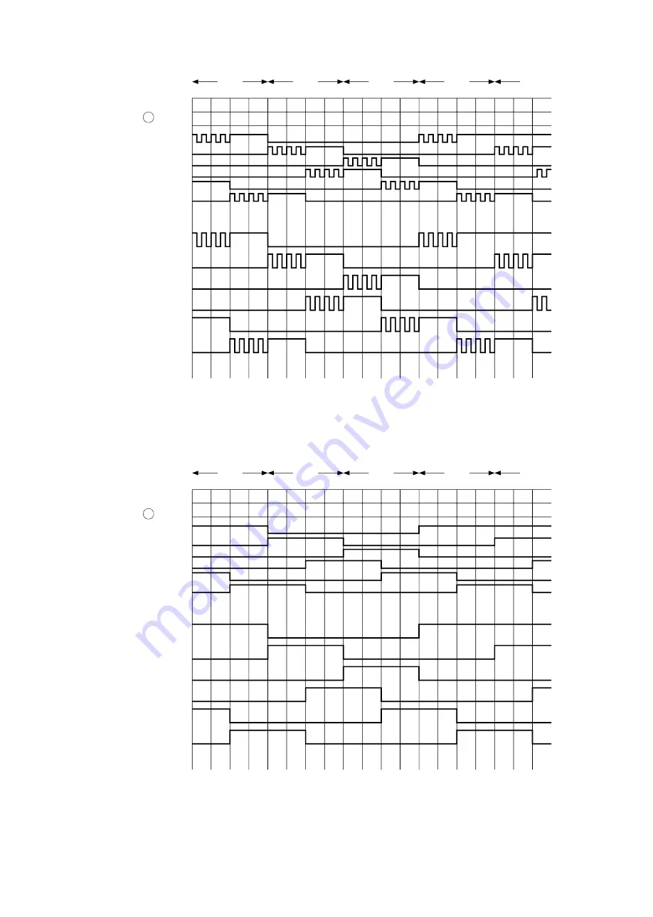
Inverter drive device (IGBT) and drive circuit are built into IPM (Intelligent Power Module). When the unit operates at low speed, chopper signal is output from the microcomputer as shown in Fig. 4-2. (0V
-5V)
The signal is converted to 0-15V inside the IPM to drive the IGBT
of each phase.
When the unit operates at high speed, drive signal is output from the microcomputer as shown in Fig. 4-3. (Microcomputer does not output a chopper signal to obtain high speed operation.) When the inverter drives and the peak current is detected, IPM outputs Fail signal (Pin
24
:
Active Lo), and lower arm IGTB is forcibly turned of
f inside IPM at the same time.
At this time, all microcomputer
signals of upper and lower arms are shut of
f by IC9 and D501.
4.Drive circuit
Microcomputer
Inverter drive device and drive IC built-in
Compressor motor
Fig. 4-1
Fail signal
U
−
U
−
V
+
W
−
U
+
V
−
W
+
U
−
V
+
W
−
U
+
120
°
120
°
120
°
120
°
120
°
V
−
V
+
W
−
U
+
V
−
W
+
U
−
V
+
W
−
U
+
V
−
5V
0V
V
+
W
+
U
−
U
+
15V
0V
U
+
V
−
W
−
V
+
W
+
V
−
W
−
5V
0V
V
+
W
+
U
−
U
+
15V
0V
U
+
V
−
W
−
V
+
W
+
V
−
W
−
Fig. 4-2
Fig. 4-3
〈
In low speed operation
〉
〈
In high speed operation
〉
Drive signal at point A
Internal drive signal of IGBT
Drive signal at point A
Internal drive signal of IGBT
120
°
120
°
120
°
120
°
120
°
- 53 -


