3
8
Notice
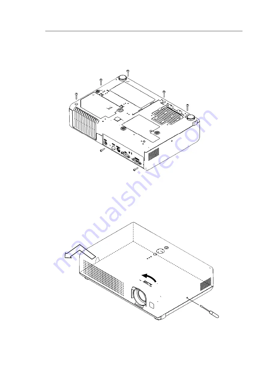
1. Removes the UPPER CASE assembly
(1) Turn over the projector slowly, so that the bottom is facing up.
(2) Unscrew five tapping screws on the bottom and 2 merter screws on the rear.
(3) Turn the focus ring in the direction shown in the figure to shift the lens inward.
(4) Stick a hard and thin stick into a hole (2mm in diameter) on the right side of the projector to unclip the
UPPER CASE assembly from the BOTTOM CASE assembly. (They will be separated with about 2mm
gap.)
(5) Shift the hole part around the AC inlet forward and upward.
Summary of Contents for Performa CP-RS55
Page 27: ... CP RS55 only ...
Page 28: ... for CP RS55 only ...
Page 36: ...36 8 Disassembly diagram ...
Page 37: ...37 ...
Page 54: ...54 12 Connector connection diagram Connector connection diagram C12S ...
Page 57: ...1 2 3 4 5 6 6 1 2 3 4 5 D G F E C B A POWER UNIT CIRCUIT C12S ...
Page 58: ...1 2 3 4 5 6 6 1 2 3 4 5 D G F E C B A PWB assembly MAIN 1 C12S ...
Page 59: ...1 2 3 4 5 6 6 1 2 3 4 5 D G F E C B A PWB assembly MAIN 2 C12S ...
Page 60: ...1 2 3 4 5 6 6 1 2 3 4 5 D G F E C B A PWB assembly MAIN 3 C12S ...
Page 61: ...1 2 3 4 5 6 6 1 2 3 4 5 D G F E C B A PWB assembly MAIN 4 C12S ...
Page 62: ...1 2 3 4 5 6 6 1 2 3 4 5 D G F E C B A PWB assembly MAIN 5 C12S ...
Page 63: ...1 2 3 4 5 6 6 1 2 3 4 5 D G F E C B A PWB assembly MAIN 6 C12S ...
Page 64: ...1 2 3 4 5 6 6 1 2 3 4 5 D G F E C B A PWB assembly MAIN 7 C12S ...
Page 65: ...1 2 3 4 5 6 6 1 2 3 4 5 D G F E C B A PWB assembly MAIN 8 C12S ...
Page 66: ...1 2 3 4 5 6 6 1 2 3 4 5 D G F E C B A PWB assembly MAIN 9 C12S ...
Page 67: ...1 2 3 4 5 6 6 1 2 3 4 5 D G F E C B A PWB assembly MAIN 10 C12S ...
Page 68: ...1 2 3 4 5 6 6 1 2 3 4 5 D G F E C B A PWB assembly MAIN 11 C12S ...


