background image

--- 24 ---

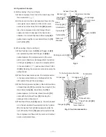
(b) Reassembly

Disassembly procedures should be followed in the reverse order.  Note the following points:

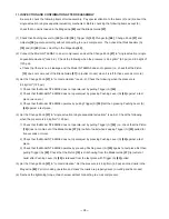
 Be extremely careful to prevent the entry of foreign particles into the control valve section.

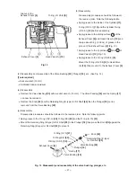
 Thoroughly apply grease to the O-ring (I.D 1.8) 

[69]

 on Plunger (A)

 [68]

, O-ring (S-4) 

[64]

, O-ring (I.D 8.8) 

[63]

and O-ring (I.D 11) 

[66] 

on Valve Piston (B) 

[65]

, and the shaft of Plunger (A) 

[68]

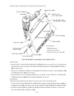
 as shown in Fig. 19.

 As shown in Fig. 19, install Valve Bushing (A) 

[70]

 so that the roll pin groove in Valve Bushing (A) 

[70]

 will be

aligned with the roll pin hole in the Body Ass’y 

[30]

.  First, insert a roll pin puller (3 mm (.118") dia.) into the roll

pin hole.  Then, upon confirming that the puller passes through the hole, drive in the Roll Pin D3 x 28 

[54]

.

If an attempt is made to drive the roll pin with force when the roll pin groove in Valve Bushing (A) 

[70]

 is

not aligned with the roll pin hole in the Body Ass’y 

[30]

, it will damage the periphery of Valve Bushing (A)

[70]

 and prevent disassembly or reassembly.

 After assembling, check that Plunger (A) 

[68]

 moves smoothly.

Body Ass’y 

[30]

Fig. 19

Roll pin hole

Roll pin groove

Valve Bushing (A) 

[70]

Assemble

Roll Pin D3 x 28 

[54]

Plunger (A) 

[68]

Valve Bushing (A) 

[70]

Coat the O-ring
groove's shaft with
grease.

Apply grease to the stem.

Summary of Contents for NT 65MA3

Page 1: ...TECHNICAL DATA AND SERVICE MANUAL FINISH NAILER NT 65MA3 SPECIFICATIONS AND PARTS ARE SUBJECT TO CHANGE FOR IMPROVEMENT LIST No E036 Sep 2006 N MODEL NT 65MA3 Hitachi Power Tools ...

Page 2: ...symbol s is are used in the place of company name s and model name s of our competitor s The symbol s utilized here is are as follows Symbols Utilized Competitors Company Name Model Name SENCO FP41XP R BOSTITCH N62FNK 2 Q PORTER CABLE DA250B P DEWALT D51275K S ...

Page 3: ...nism 8 8 2 Interchangeability 10 8 3 Operation Principle 11 9 TROUBLESHOOTING GUIDE 14 9 1 Troubleshooting and Correction 14 9 2 Regrinding the Driver Blade 16 9 3 Possible Causes and Correction of Air Leakage 17 10 DISASSEMBLY AND REASSEMBLY 19 10 1 General Precautions in Disassembly and Reassembly 19 10 2 Disassembly and Reassembly of the Output Section 20 10 3 Disassembly and Reassembly of the ...

Page 4: ... kg 3 APPLICATIONS For manufactured housing on site and mobile home construction Mounting of light and heavy trim Installation of molding paneling and stairways Assembling of window and door casings For cabinet making furniture making and woodworking 4 SELLING POINTS Simple drive depth adjusting mechanism Single actuation contact actuation selector Grip rubber Capable of cleaning chips and sawdust...

Page 5: ...mm 13 1 2 x 12 x 3 Spiral spring 100 nails 1 20 ltr cycle at 6 9 bar 1 20 ltr cycle at 7 kgf cm2 042 ft3 cycle at 100 psi 1 4 NPT thread Corrugated cardboard box 430 mm x 380 mm x 113 mm 16 15 16 x 14 15 32 x 4 7 16 Safety glasses Code No 875769 1 Case Code No 881775 1 Nose cap Code No 881751 1 Full sequential actuation mechanism kit Code No 884320 Sequential trip mechanism kit Pneumatic tool lubr...

Page 6: ...igger next press the pushing lever against the wood to drive the nail After nailing once nailing will not be possible again until the trigger is released and pressed again CONTACT ACTUATION MECHANISM First press the pushing lever against the wood next pull the trigger to drive the nail First pull the trigger next press the pushing lever against the wood to drive the nail If the trigger is held bac...

Page 7: ... Other nails will cause clogging of nails and subsequent damage to the nailer 15 gauge finish nail collating angle 34û Min Max Fig 1 Dimensions of nails 5 4 Examples of Nail Use Examples of uses for the nails shown in 5 2 for installing finish materials or molding as shown in Fig 2 Typical mounting methods are shown in circles A and B A Crown molding B Base molding Fig 2 Examples of molding ...

Page 8: ...quired nailing energy Nailer output energy P S NT 65MA NT 65MA2 NT 65MA3 Plywood 12 mm 472 thick x 6 Fig 3 Required nailing energy and nailer output energy 5 6 Optional Accessories Full sequential actuation mechanism kit sequential trip mechanism kit Code No 884320 A full sequential actuation mechanism kit sequential trip mechanism kit is provided as an optional accessory for the Model NT 65MA3 By...

Page 9: ...5 mm x 95 mm 12 29 32 x 12 x 3 3 4 None None Single touch operation by hand Horizontal dial Rubber 34û 2 4 mm to 3 0 mm 095 to 12 25 mm to 65 mm 1 to 2 1 2 4 9 to 8 3 bar 5 to 8 5 kgf cm 2 70 to 120 psi 1 2 ltr cycle 042 ft 3 cycle 100 nails Rear loading type Angle 34û 2 1 kg 4 6 lbs R Easily changeable 360û by turning by hand 295 mm x 254 mm x 83 mm 11 5 8 x 10 x 3 9 32 None None Single touch ope...

Page 10: ...ot nailer is optionally available and recommend it to the customers who want to use it Refer to the leaflet attached together with the Instruction Manual for details 7 1 Instruction Manual Although every effort is made in each step of the design manufacture and inspection to provide protection against safety hazards the dangers inherent in the use of any pneumatic tool cannot be completely elimina...

Page 11: ...ned below The U S A OSHA ANSI SNT 101 2002 1926 102 Eye and face protection 1926 302 Power operated hand tools Portable Compressed Air Actuated Fastener Driving Tools Safety Requirements for 8 MECHANISM AND OPERATION PRINCIPLE 8 1 Mechanism As illustrated in Fig 4 the Model NT 65MA3 can be generally divided into four sections output section control valve section driving section and magazine sectio...

Page 12: ... 11 Piston Bumper 25 Knob 24 Trigger A 53 Body Ass y 30 Magazine section Nail Feeder B 80 Magazine 82 Nail Rail 79 Magazine Cover 76 Nail Feeder A 74 Valve Piston B 65 Valve Bushing B 61 Switching Device Change Knob 57 Fig 4 Construction Control valve section Plunger Spring 67 Valve Bushing A 70 Plunger A 68 Control valve section Blow nozzle section Cap A 49 Nail Stopper 81 Pushing Lever A 40 Lock...

Page 13: ...le though their code numbers are different are described in detail Parts that are not interchangeable with those of the Model NT 65MA2 NT 65MA3 NT 65MA2 Color Green Parts Top Cover 3 Newly designed Exhaust Cover 5 Newly designed Gasket 6 Newly designed Newly designed Body Ass y 30 Magazine 82 Color Green Color Black Protector Cap A 49 Color Black Color Black Color Silver green Color Black Color Si...

Page 14: ... 2 When the exhaust valve opens the compressed air in the head valve chamber is discharged into the atmosphere through the air passage 3 When the air pressure applied on the bottom surface of Head Valve A 10 overcomes the strength of the Head Valve Spring 8 Head Valve A 10 is pushed upward At this time Head Valve A 10 seals with the Exhaust Cover 5 blocking the passage to the exhaust vent 4 When H...

Page 15: ...pen the exhaust vent 4 The compressed air at the upper portion of the Piston 15 is discharged into the atmosphere through the exhaust vent In this way the air pressure at the upper portion of the Piston 15 is reduced and the greater pressure of the air accumulated in the return air chamber pushes the Piston 15 upward 5 If the air pressure at the lower portion of the Piston 15 is higher than that o...

Page 16: ...iston lower chamber and Valve Piston B 65 is forced upward The Piston 15 then returns fully upward Therefore unless Trigger A 53 is released after each nailing operation the structural mechanism prevents the next nailing operation Contact actuation mechanism Switching device downward position 1 Immediately after the first nail is driven the control valve should be as shown in Fig 8 2 Even when onl...

Page 17: ...pring is abnormal fatigued or damaged Correct the burred or deformed portion Replace the part Replace the part Nail rail groove width too wide or too narrow Nail groove in the blade guide is abnormal burrs deformed or damaged Magazine cover is abnormal deformed or damaged Adhesive fragments and wood chips are on the magazine nail feeder or nail rail Check if they move smoothly after loading nails ...

Page 18: ...ade Replace the O ring Replace the part Apply grease Disassemble the output section and check the O ring and the inside of the cylinder for abnormality Control valve section Plunger A valve piston B valve bushing A or valve bushing B is abnormal seized or damaged Disassemble the control valve section and check the O rings 2 Nails are driven but bent Unspecified nails are used Driver blade is worn ...

Page 19: ...iston driver blade etc Check each part for abnormalities worn damaged deformed etc 6 Air keeps blowing from the nose of the blow nozzle O ring in valve piston B is worn Replace the part Abnormal plunger A trigger arm A pushing lever B and or body worn or damaged The position of a switching device is mistaken The position of a switching device is checked A switching device is set to the correct pos...

Page 20: ...n is deformed or clogged with dust Air leakage point Possible cause With control valve OFF With control valve ON B Exhaust cover Repair procedure 1 Check the points of the following parts marked by an asterisk for abnormal condition 2 Next check the seal parts marked with a double circle for wear flaws and damage 3 And then check other places Head Valve A 10 and the Cylinder 11 are abnormal seal s...

Page 21: ...nger A 68 is abnormal worn broken or damaged Valve Bushing A 70 is abnormal sliding surface of Plunger A 68 is deformed or scratched The Piston Bumper 25 is abnormal d or e portion is damaged deformed or cracked The Piston 15 is abnormal driver blade or sealed face is deformed The e surface of the Body Ass y 30 is deformed The upper O Ring I D 8 8 63 on Valve Piston B 65 is abnormal worn broken or...

Page 22: ...bly Apply grease ATTOLUB No 2 Code No 317918 to the O rings and O rings sliding portions When installing the O rings be careful not to damage the O rings and prevent dirt entry Oil required Hitachi pneumatic tool lubricant 30 cc 1 oz Oil feeder Code No 877153 120 cc 4 oz Oil feeder Code No 874042 1 ltr 1 quart Can Code No 876212 If the Gasket 6 is damaged replace it and check that no air is leakin...

Page 23: ...ench 4 mm and remove the Exhaust Cover 5 Then the components of the output section such as the Cylinder 11 Piston 15 and Piston Bumper 25 with the Bumper Sheet 26 assembled can be removed Remove the Hex Socket Hd Bolt M6 x 12 1 with a hex bar wrench 5 mm The Plate 2 and the Top Cover 3 can now be removed Hex Socket Hd Bolt M6 x 12 1 Plate 2 Top Cover 3 Exhaust Cover 5 Hex Socket Hd Bolt W Sp Washe...

Page 24: ...ft 23 to mount it b Reassembly Disassembly procedures should be followed in the reverse order Note the following points Apply grease to the inside of the Cylinder 11 O ring I D 34 7 14 and the Cylinder O ring I D 63 1 12 before reassembly Apply grease to the sliding surface a of the Exhaust Cover 5 and Head Valve A 10 and charge about 0 5 g 018 oz of grease in the groove of the Exhaust Cover 5 Fig...

Page 25: ...Pushing Lever B 36 Remove Trigger A 53 Force down Screwdriver Fig 16 Plunger A 68 O ring S 4 64 Head Valve O ring I D 16 8 60 Change Knob 57 Trigger A 53 Spring C 56 Carefully disassemble so as not to lose these parts a Disassembly Remove the Retaining Ring E type for D6 Shaft 27 with the blade of a screwdirver and pull out the Change Knob 57 being careful not to lose the Steel Ball D3 97 55 and S...

Page 26: ...t to damage Valve Piston B 65 Valve Bushings A 70 and B 61 etc Do not pull out the end of Plunger A 68 with pliers 3 To take out Valve Bushing B 61 put a 1 5 to 3 mm 059 to 118 dia wire with its end hooked into the hole in the bushing and pull it out while being careful not to damage the internal surface of Valve Bushing B 61 as shown in Fig 18 Push 4 to 5 mm 157 to 197 dia bar Body Ass y 30 Head ...

Page 27: ... the roll pin hole in the Body Ass y 30 First insert a roll pin puller 3 mm 118 dia into the roll pin hole Then upon confirming that the puller passes through the hole drive in the Roll Pin D3 x 28 54 If an attempt is made to drive the roll pin with force when the roll pin groove in Valve Bushing A 70 is not aligned with the roll pin hole in the Body Ass y 30 it will damage the periphery of Valve ...

Page 28: ...the two Hex Socket Hd Bolts M6 x 30 32 with the hex bar wrench 5 mm Now the Blade Guide 37 Guide Plates A 33 and B 31 Pushing Lever B 36 etc can be removed Remove the two Ratchet Springs 39 from the Adjuster 38 with the small flat blade screwdriver being very careful not to lose them Now the Adjuster 38 can be removed from Pushing Lever B 36 Nylon Nut M5 44 Sleeve 45 Body Ass y 30 Blade Guide 37 G...

Page 29: ...ter making the Blade Guide 37 Guide Plates A 33 and B 31 flush with the Body Ass y 30 After assembly check that Pushing Levers A 40 B 36 and the Adjuster 38 move smoothly 10 5 Disassembly and Reassembly of the Cap and the Magazine Section 1 Disassembly and reassembly of the cap See Fig 21 Tool required Hex bar wrench 4 mm a Disassembly Remove the three Hex Socket Hd Bolts M5 x 16 50 with the hex b...

Page 30: ...d the Ribbon Spring 72 Nail Feeders A 74 B 80 and Nail Rail 79 can be taken out Remove the two Machine Screws M5 x 15 Black 77 with the Phillips screwdriver so that the Magazine 82 and the Magazine Cover 76 can be removed Pull out the Roll Pin D2 5 x 20 Stainless 73 with the roll pin puller 2 5 mm 098 dia so that Nail Feeder A 74 Nail Feeder B 80 and the Pushing Spring 75 can be removed b Reassemb...

Page 31: ... operate just by pulling Trigger A 53 2 Check that the Model NT 65MA3 does not operate just by pressing Pushing Lever A 40 against a test piece wood etc 3 Check that the Model NT 65MA3 operates by pulling Trigger A 53 first then pressing Pushing Lever A 40 against a test piece 4 Set the Change Knob 57 to single actuation single sequential actuation see 5 2 Check the following when the pressure is ...

Page 32: ...General Assembly Pushing Lever B Holder Spring Adjuster Pushing Lever A Piston O ring Trigger A Pushing Lever Guide Valve Bushing B Valve Piston B Plunger Spring Plunger A Valve Bushing A Head Valve O ring O ring x 6 Adjustment Cylinder Body Valve Guide Plate B Guide Plate A Blade Guide Magazine Magazine Cover Nail Feeder A Nail Rail Nail Feeder B Body Cylinder Cylinder O ring O ring Piston Bumper...

Page 33: ... Hitachi Power Tools 1 2 3 4 5 6 7 8 9 10 11 12 13 14 15 16 17 18 19 20 21 22 23 24 25 26 27 28 29 30 31 32 33 42 34 43 35 36 37 38 39 40 41 44 45 46 47 48 49 50 51 52 54 53 55 56 57 54 58 59 60 61 62 63 64 65 63 66 67 68 69 70 71 72 73 74 75 78 76 77 81 80 79 44 82 501 502 503 504 ...

Page 34: ...2 701 VALVE BUSHING 1 23 968 643 RETAINING RING E TYPE FOR D4 SHAFT 1 24 884 334 KNOB 1 25 881 741 PISTON BUMPER 1 26 881 756 BUMPER SHEET 1 27 955 479 RETAINING RING E TYPE FOR D6 SHAFT 1 28 NAME PLATE 1 29 NAME PLATE B 1 30 885 963 BODY ASS Y 1 INCLUD 46 31 881 764 GUIDE PLATE B 1 32 949 661 HEX SOCKET HD BOLT M6X30 10 PCS 2 33 881 743 GUIDE PLATE A 1 34 884 323 LOCK LEVER 1 35 877 894 HOLDER SP...

Page 35: ... 885 O RING S 18 1 63 878 925 O RING I D 8 8 2 64 981 317 O RING S 4 1 65 884 143 VALVE PISTON B 1 66 878 887 O RING I D 11 1 67 884 966 PLUNGER SPRING 1 68 884 144 PLUNGER A 1 69 878 888 O RING I D 1 8 1 70 884 341 VALVE BUSHING A 1 71 LABEL 1 72 881 755 RIBBON SPRING 1 73 881 767 ROLL PIN D2 5X20 STAINLESS 1 74 881 746 NAIL FEEDER A 1 75 880 321 PUSHING SPRING 1 76 881 752 MAGAZINE COVER 1 77 88...

Page 36: ...SAFETY GLASSES 1 502 884 340 CASE 1 503 884 337 CAUTION TAG 1 FOR USA CAN 504 885 244 LEAFLET 1 FOR USA CAN 601 884 320 FULL SEQUENTIAL ACTUATION MECHANISM KIT 1 INCLUD 602 606 602 884 321 TRIGGER A 1 603 881 778 PLUNGER B 1 604 878 888 O RING I D 1 8 1 605 880 672 VALVE PISTON B 1 606 884 322 TRIGGER PIN 1 607 881 768 GRIP TAPE A 1 608 880 407 TAPE 2 Printed in Japan 060912N ...

Page 37: ......
Reviews: