


--- 41 ---
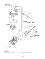
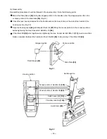
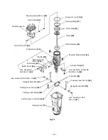
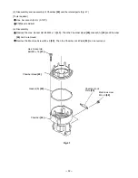
(2) Disassembly and reassembly of the housing section (Fig. 33)
[Tools required]
Hex. bar wrench (3 mm (0.118"), 4 mm (0.157"))
Spaner (7 mm (0.276") or slender hd. pliers
Roll pin puller (3 mm (0.118"))
Phillips screwdriver
Retaining ring puller for C-type hole
Small flat-blade screwdriver
(a) Disassembly
Remove the Seal Lock Hex. Socket Hd. Bolt M5 x 10
[58]
to remove the Cylinder plate
[57]
.
Remove the Machine Screw M4 x 6
[33]
to remove the Switch Plate
[34]
. Note that the Cylinder Ass'y
[42]
cannot be removed from the Housing Ass'y
[74]
without removing the Switch Plate
[34]
.
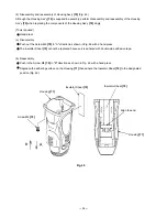
Push the tip of the Cylinder Ass'y
[42]
in the Housing Ass'y
[74]
. Then the Cylinder Ass'y
[42]
, chamber
section, Pushing Lever Arms (A)
[60]
and (B)
[62]
can be removed from the Housing Ass'y
[74]
in a single unit.
It is easy to remove them while pressing the side of the Housing Ass'y
[74]
with a hand (Fig. 34).
Remove the two Pushing Lever Springs
[63]
with a hand.
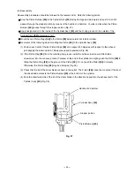
Remove the two Roll Pins D3 x 32
[25]
with a roll pin puller to remove the chamber section from the Cylinder
Ass'y
[42]
.
Secure the U-Nut M4
[59]
with a spanner (7 mm (0.276")) or slender hd. pliers and loosen the Hex. Socket Hd.
Bolt M4 x 10
[61]
. Then Pushing Lever Arms (A)
[60]
and (B)
[62]
are separated from the Pushing Lever
Connector
[68]
and they can be removed from the Cylinder Ass'y
[42]
.
Remove the O-ring (I.D. 66.27)
[36]
and two Chamber Stop Rubbers
[41]
with a hand.
Remove the two Hex. Socket Hd. Bolts M4 x 10
[43]
. Then the muffler section can be disassembled into
Buffer Cover
[44]
, Lead Valve
[45]
and Muffler
[50]
.
Note that a special sealant is used for the Cylinder Ass'y
[42]
. Select a liquid silicon sealant capable of
resisting temperatures up to 300
û
C.