background image

ELECTRIC  TOOL  PARTS  LIST

LIST NO. E495

HAMMER
Model  H  45MRY

2006 

  8 

3

(E1)

 Hitachi Power Tools

A

A

111

57

63

74

122

1

2

3

4

5

6

7

8

6

9

3

10

11

12

14

15

16

17

18

19

20

21

22

23

24

27

28

29

30

31

32

33

34

35

36

39

40

41

37

42

38

43

44

45

46

47

51

52

53

54

55

56

58

59

48

49

50

60

61

62

64

65

67

106

107

108

109

110

112

113

114

115

116

117

118

119

120

121

55

68

69

69

70

70

71

72

73

76

75

77

78

79

80

89

90

82

83

85

82

83

86

87

88

91

92

93

94

95

97

98

99

100

101

102

103

104

105

82

83

82

83

81

96

66

13

25

501

502

Summary of Contents for H45MRY

Page 1: ...TECHNICAL DATA AND SERVICE MANUAL DEMOLITION HAMMER H 45MRY SPECIFICATIONS AND PARTS ARE SUBJECT TO CHANGE FOR IMPROVEMENT LIST No E495 Oct 2006 H MODEL H 45MRY Hitachi Power Tools ...

Page 2: ...L DATA AND SERVICE MANUAL symbols are used in the place of company names and model names of our competitors The symbols utilized here are as follows Symbols Utilized Competitors Company Name Model Name BOSCH GSH5E B MAKITA HM0860C C ...

Page 3: ...7 3 O ring Replacement 10 8 REFERENCE INFORMATION 11 8 1 Striking Operation 11 8 2 Dynamic Damper with Leaf Spring 12 8 3 Vibration proof Handle thanks to the Transatory Unit and the Neidhardt Spring 12 8 4 Idling proof Mechanism 13 8 5 Shock absorbing Mechanism 14 8 6 Sealed and Dustproof Construction 14 8 7 Tool Retainer 15 8 8 Adjusting Mechanism for the Tool Swivel Angle 15 8 9 Side Handle 16 ...

Page 4: ...re as follows 1 Lowest vibration level in the class thanks to the dynamic damper with a leaf spring and the new vibration absorbing handle 2 High chipping and demolishing performance with low vibration and noise level 3 Self chiseling Good feeling 4 A highly reliable mechanism for prevention of idle hammering and shock absorbing mechanism results in prolonged service life and comfortable operation...

Page 5: ...ck absorbing mechanism results in prolonged service life and comfortable operation Large trigger switch for comfortable operation Soft touch grip for easier handling Vibration reduction mechanism D type side handle with adjustable mechanism for 360û rotation plus positioning from front to rear Simply turning method variable lock mechanism for easy working angle adjustment of chisels etc Newly desi...

Page 6: ...uantity of body jumping is less than that of the current Model H 45MR and the working tool smoothly penetrates into the workpiece with a light pressing force The Model H 45MRY realizes quicker self chiseling with better feeling Maximum compressed air force piston force Demolished amount Quantity of body jumping About 32 down About 20 up About 24 down 4 1 4 Vibration reduction mechanism The Model H...

Page 7: ...ng the bull point from the concrete by moving the main body up the second hammer contacts hammer holder A and the cushion damper A provided between hammer holder A and the front cover absorbs the hammering force of the second hammer Thus the Model H 45MRY has greater durability than the similar products 4 1 7 D type side handle with adjustable mechanism for 360û rotation plus positioning from fron...

Page 8: ...gger switch with stopper D shaped handle and side handle 9 1A 110 V 4 4 A 230 V 950 W No load 4 000 min 1 Full load 3 000 min 1 Product 5 9 kg 13 0 lbs Excluding cord and side handle Packed 12 4 kg 27 3 lbs Corrugated cardboard box with plastic tool case Bull point 280 mm 11 1 32 1 pc Side handle 1 pc Plastic tool case 1 pc Single phase AC 50 60 Hz Power source Voltage Motor type Insulation struct...

Page 9: ... work Code No 313471 313472 1 Cold chisel SDS max shank type Overall length 280 mm 11 1 32 400 mm 15 3 4 Code No 313473 313474 Overall length 280 mm 11 1 32 400 mm 15 3 4 3 Cutting and stripping work Asphalt cutting etc 1 Cutter SDS max shank type Overall length 400 mm 15 3 4 Width 50 mm 2 Code No 313475 ...

Page 10: ... Scoop SDS max shank type 5 Roughing surface work Overall length 220 mm 8 21 32 Code No 313479 1 Bushing tool 2 Shank SDS max shank type Code No 313477 6 Tamping work Overall length 220 mm 8 21 32 Code No 313479 1 Rammer 2 Shank SDS max shank type Code No 313478 150 mm x 150 mm ...

Page 11: ...d hammer drill 500 g 1 1 lbs Can Code No 980927 70 g 2 5 oz Tube Code No 308471 30 g 1 oz Tube Code No 981840 NOTE Code numbers listed above are subject to change without notice Please refer to periodic Technical News Bulletins ...

Page 12: ...g 1 are obtained in actual factory tests and are for reference only Demolished amount may vary in accordance with operating conditions operator skill etc dB Full load noise level Length Height Width mm mm mm H 45MRY 950 12 7 3 000 7 7 202 4 99 5 9 13 0 lbs H 45MR 475 18 45 64 230 9 1 6 104 4 3 32 B C Fig 1 Vibration reduction mechanism Vibration absorbing handle Double insulation 950 12 5 3 000 14...

Page 13: ...portion and the speed reduction portion of the Model H 45MRY respectively use different types of grease Grease replacement is required if the unit is disassembled for maintenance or O rings become damaged and worn as described in 7 3 The striking portion uses special grease If the striking portion inside the cylinder crank case is disassembled thoroughly remove all of the old grease from each part...

Page 14: ...trike against the end of the second hammer At the same time the air cushion effect within the air chamber absorbs the impact of the striker Should the air escape from the air chamber the air cushion effect would cease and the impact energy would not be absorbed Accordingly the O rings mounted on the striker and the piston play an extremely important role in sealing air within the air chamber Secon...

Page 15: ... Slotted groove Handle damper retaining material Cylinder crank case Pressing force of the main body a At no load Rolled and compressed Reaction Fig 4 Vibration of the main body Vibration of the weight Vibration of the weight Vibration of the main body Structure of the transatory unit The main body cylinder crank case is connected to the upper handle through four cylindrical rubbers handle dampers...

Page 16: ...om being pulled out Fig 5 Compressed by turning Rebound Turning direction of the handle Fig 5 8 4 Idling proof Mechanism When the bull point is released from the concrete surface the slide sleeve and the second hammer are forcibly moved to the position illustrated in Fig 6 by spring B and the striker moves out of striking position When this occurs the air holes located at the position unaffected b...

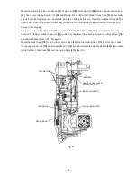
Page 17: ... Model H 45MRY is greatly increased because the second hammer does not strike the tool retainer directly Fig 7 Second hammer Hammer holder A Damper A Fig 8 Front cover Vibration absorbing unit Retainer sleeve Switch handle O ring O ring O ring O ring Housing Cylinder crank case Vibration absorbing unit Oil seal 8 6 Sealed and Dustproof Construction The cylinder crank case is sealed by five O rings...

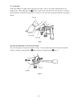
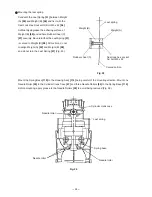
Page 18: ...he groove position by turning the tool and push it in to the end Lock the tool by returning grip A back to the original position Fig 9 Grip A Front cap Tool shank A 8 8 Adjusting Mechanism for the Tool Swivel Angle The tool swivel angle can be easily changed in 12 steps The tool swivel angle can be set freely to the desired position by pushing out grip B ahead in A direction and then turning grip ...

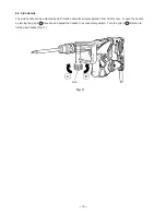
Page 19: ...e adjusted by 360û rotation and also allows operation from front to rear Loosen the handle by turning the grip in A direction and adjust the handle to a convenient position Turn the grip in B direction to fix the side handle Fig 11 Fig 11 Grip ...

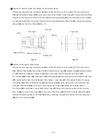
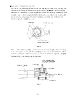
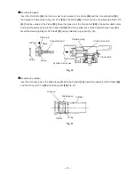
Page 20: ...four Steel Balls D6 35 10 can be removed from the Front Cover 12 Furthermore remove the Retaining Ring D42 6 by means of a snap ring remover then Grip C 9 can be removed from the Front Cover 12 Fig 13 Retaining ring Needle roller D8 x 20 2 pcs Needle holder 9 1 1 Disassembly Retainer disassembly See Figs 12 and 13 Pull Grip A 2 fully in the arrow direction as shown in Fig 12 and remove the Front C...

Page 21: ...12 Then the Front Cover 12 Retainer Sleeve 16 Second Hammer 21 Hammer Holder B 24 Damper B 25 Hammer Holder C 27 Damper C 22 and Sleeve A 23 can be removed from the Cylinder Crank Case 47 The Cylinder 30 Striker 28 Slide Sleeve 31 and Spring B 32 are remained in the Cylinder Crank Case 47 Lightly tap the Front Cover 12 side of the Cylinder Crank Case 47 with a plastic hammer to remove the Cylinder...

Page 22: ...ank Shaft 42 as shown in Fig 16 so that the hole of the Retaining Ring for D40 Hole 43 can be seen Fig 16 Crank Shaft Hole of the Retaining Ring for D40 Hole 43 Cylinder crank case Place the Cylinder Crank Case 47 on a workbench facing the Connecting Rod 36 side downward Apply light pressure on the end surface of the Crank Shaft 42 with a hand press to remove the First Gear 60 and the Crank Shaft ...

Page 23: ... Front cover Proper jig Mounting the first gear and the crank shaft Mount the O ring S 40 44 to the Cylinder Crank Case 47 Press fit the Ball Bearing 6203DDCMPS2L 45 and mount the Retaining Ring for D40 Hole 43 using a retaining ring puller Press fit the Crank Shaft 42 in the Ball Bearing 6203DDCMPS2L 45 and mount the Oil Seal 46 Put one Feather Key 4 x 4 x 10 38 in the groove of the Crank Shaft 4...

Page 24: ...ing Rod 36 then press fit it Mount the O ring I D 27 2 33 to the Piston 35 At this time do not protrude the Piston Pin 34 from the outside of the Piston 35 Move the crank pin of the Crank Shaft 42 to the bottom dead center and insert the piston ass y into the Crank Shaft 42 from the cylinder case of the Cylinder Crank Case 47 Mount the Retaining Ring for D10 Shaft 37 using a retaining ring puller ...

Page 25: ...rank pin of the Crank Shaft 42 then move the Piston 35 to the top dead center Insert Spring B 32 into the cylinder case of the Cylinder Crank Case 47 then insert the assembly of the Cylinder 30 Slide Sleeve 31 and Striker 28 into the Cylinder Crank Case 47 Fig 22 Fig 22 Cylinder Crank shaft Cylinder crank case Striker Spring B Piston Slide sleeve Crank pin portion 0 05 convex line ...

Page 26: ...protrude from the main body and the Holder 88 does not protrude from the end surface of the Back Cover 76 Check that the convex mark of the Back Cover 76 aligns with the convex mark of the Handle Shaft 87 Then mount the Handle Shaft 87 and push the four Handle Dampers 86 in the clearances between the Holder 88 and the Handle Shaft 87 by hand being careful not to protrude the Handle Dampers 86 from...

Page 27: ...t A 59 and Weight B 58 and do not turn the Leaf Spring 51 Fig 25 Fig 25 Weight B Rubber sheet C Leaf spring Curved portion Weight A Seal lock hex socket hd bolt M5 x 22 Mount the Spring Base 115 to the Housing Ass y 114 being careful of the mounting direction Mount one Needle Roller 55 to the Cylinder Crank Case 47 and three Needle Rollers 55 to the Spring Base 115 Before mounting apply grease to ...

Page 28: ...pply grease to Spring Bumper B 75 and mount it to the Back Cover 76 being careful of the mounting direction To replace Rubber Sheet A 74 sufficiently degrease the adhering surface of the Back Cover 76 and adhere Rubber Sheet A 74 securely Mount the Back Cover 76 to the Cylinder Crank Case 47 and the Housing Ass y 114 At this time check that Spring Bumper B 75 and Rubber Sheet A 74 are adhered and ...

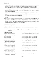
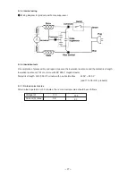
Page 29: ... the Gear Cover Ass y 62 9 1 3 Screw locking agent TB1401 Apply screw locking agent TB1401 to all hex socket hd bolts M4 M5 and M6 CAUTION If bolts are loosened by vibration they could cause damage to the hammer body Ensure without fail that screw locking agent is applied to the threaded portions of the bolts prior to reassembly 9 1 4 Tightening torque 1 Attached bolts of the front cover 13 7 1 96...

Page 30: ... and repair measure the insulation resistance and the dielectric strength Insulation resistance 7 M Ω or more with DC 500 V megohm tester Dielectric strength AC 4 000 V 1 minute with no abnormalities 220 V 240 V and 110 V for U K products 9 1 7 No load current value After no load operation for 30 minutes the no load current value should be as follows 230 2 1 ...

Page 31: ...er Front Cover O ring O ring Retainer Sleeve Spring A Damper A Hammer Holder A O ring Second Hammer Damper B Damper A Hammer Holder B Hammer Holder C Armature Ass y Ball Bearing 6201DD Ball Bearing 608VV Dust Washer B Washer A Bearing Holder O ring Back Cover Leaf Spring Spring Bumper A Rubber Sheet C Weight B Weight A Spring Bumper B General Assembly Crank Cover O ring Crank Shaft Feather Key Bal...

Page 32: ...7 18 19 20 21 22 23 24 27 28 29 30 31 32 33 34 35 36 39 40 41 37 42 38 43 44 45 46 47 51 52 53 54 55 56 58 59 48 49 50 60 61 62 64 65 67 106 107 108 109 110 112 113 114 115 116 117 118 119 120 121 55 68 69 69 70 70 71 72 73 76 75 77 78 79 80 89 90 82 83 85 82 83 86 87 88 91 92 93 94 95 97 98 99 100 101 102 103 104 105 82 83 82 83 81 96 66 13 25 501 502 ...

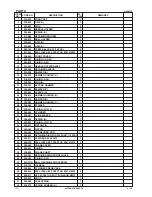
Page 33: ...1 23 326 495 SLEEVE A 1 24 320 814 HAMMER HOLDER B 1 25 320 815 DAMPER B 1 27 326 382 HAMMER HOLDER C 1 28 326 383 STRIKER 1 29 325 297 O RING I D 27 2 1 30 326 496 CYLINDER 1 31 326 497 SLIDE SLEEVE 1 32 326 498 SPRING B 1 33 325 297 O RING I D 27 2 1 34 324 917 PISTON PIN 1 35 326 384 PISTON 1 36 326 385 CONNECTING ROD 1 37 939 540 RETAINING RING FOR D10 SHAFT 10 PCS 1 38 930 511 FEATHER KEY 4X4...

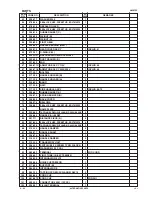
Page 34: ... ASS Y 1 INCLUD 68 72 74 326 487 RUBBER SHEET A 1 75 326 376 SPRING BUMPER B 1 76 326 505 BACK COVER 1 77 326 378 BELLOWS 1 78 306 061 SEAL LOCK HEX SOCKET HD BOLT M5X30 2 79 NAME PLATE 1 80 302 089 TAPPING SCREW W FLANGE D5X20 BLACK 4 81 326 485 HANDLE A B SET 1 82 991 711 DISTANCE PIECE B 4 83 991 690 SEAL LOCK HEX SOCKET HD BOLT M5X12 4 85 307 028 TAPPING SCREW W FLANGE D4X25 BLACK 3 86 310 124...

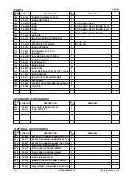
Page 35: ...08 VVM BALL BEARING 608VVC2PS2L 1 113 326 484 BEARING HOLDER 1 114 326 481 HOUSING ASS Y 1 115 326 506 SPRING BASE 1 116 935 829 BRUSH CAP 2 117 999 073 CARBON BRUSH AUTO STOP TYPE 1 PAIR 2 118 971 001 BRUSH HOLDER 2 119 938 477 HEX SOCKET SET SCREW M5X8 2 120 326 504 TAIL COVER 1 121 302 089 TAPPING SCREW W FLANGE D5X20 BLACK 2 122 326 488 COVER A 1 501 313 471 BULL POINT SDS MAX 280L 1 502 326 5...

Page 36: ......

Reviews: