background image

Setup Process

GR2K-GA-0008

 2-7

Rev. 1.00

2.6

Attaching and Detaching the Power Cable

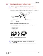
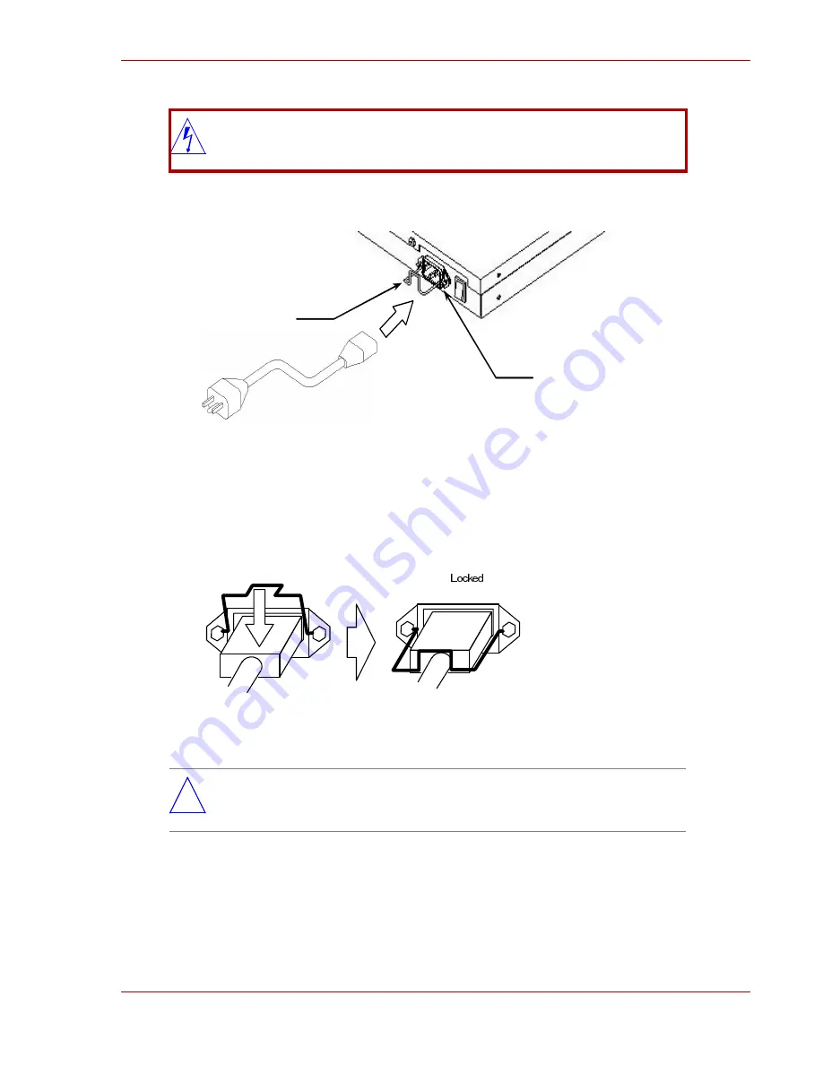
1. As shown in Figure 2-6, attach the power cable to the connector at the back of 

the GR2000-B.

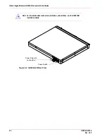
Figure 2-6  Connecting a Power Cable to the GR2000-B

2. As shown in Figure 2-7, lock the power cable connector into place on the 

GR2000-B chassis.

Figure 2-7  Locking the Power Cable into Place

DANGER:     To prevent the possibility of electric shock, use only grounded power 

outlets.


*

 Note:   When pulling a cable out of the connector, follow the procedures above in 

reverse order.


AC Connector 

Metal bail to lock 

power cable in 

place 

Power cable 

Push down the locking metal 

bail toward the direction 

indicated by the arrow in the 

figure below. 

Summary of Contents for GR2000-B Series

Page 1: ...Hitachi Gigabit Router GR2000 B Series GR2K GA 0008 Rev 1 00 Quick Start Guide ...

Page 2: ...dential area is likely to cause harmful interference in which case the user will be required to correct the interference at his her own expense The user is cautioned that changes or modifications not expressly approved by the manufacturer could void the user s authority to operate the equipment Class A Emission Statement Korea Trademarks Ethernet is a product name of Xerox Corp USA Ethernet is a t...

Page 3: ...tachi Ltd Hitachi Ltd reserves the right to make changes to this document at any time without notice and assumes no responsibility for its use All the features described in this document may not be currently available Change Record Preface This manual presents simplified procedures for unpacking setup and operating the GR2000 B models Before you begin to unpack and use the GR2000 B read the Safety...

Page 4: ... 4 BOD Bandwidth On Demand BPDU Bridge Protocol Data Unit CATV Cable Television CBR Constant Bit Rate CIDR Classless Inter Domain Routing CIR Committed Information Rate CLLM Consolidated Link Layer Management CLNP Connectionless Network Protocol CLP Cell Loss Priority CRC Cyclic Redundancy Check CR LDP Constraint Based Label Distribution Protocol CSMA CD Carrier Sense Multiple Access with Collisio...

Page 5: ...ssage protocol version6 IEEE Institute of Electrical and Electronics Engineers Inc IETF the Internet Engineering Task Force IDI Initial Domain Identifier IGMP Internet Groupe Management Protocol ILMI Interim Local Management Interface IP Internet Protocol IPv4 Internet protocolversion 4 IPv6 Internet Protocol version 6 IPv6cp Ipv6 Control Protocol IPX Internetwork Packet Exchange ISO International...

Page 6: ...MRU Maximum Receive Unit NSAP Network Service Access Point MTU Maximum Transfer Unit NBP Name Binding Protocol NCP Network Control Protocol NDP Neighber Discovery Protocol NET Network Entity Title NetBIOS Network Basic Input Output System NIF Network Interface board NRZ Non Return to Zero NSAP Network Service Access Point OC 3c Optical Carrier level 3 concatenation OC 12c Optical Carrier level 12 ...

Page 7: ...tion Protocol Next Generation RLB Remote Loop Back RM Routing Manager RPF Reverse Path Forwarding RP Routing Processor RSVP Resource Reservation Protocol SA Source Address SAP Service Access Point SD Start Delimiter SDH Synchronous Digital Hierarchy SDLC Service Advertising Protocol SD I Super Digital I interface SFD Start Frame Delimiter SMF Single Mode Fiber SNA Systems Networking Architecture S...

Page 8: ...ernet Protocol TOS Type Of Service TTC Telecommunication Technology Committee TTL Time To Live UBR Unspecified Bit Rate UDP User Datagram Protocol UNI User Network Interface VBR Variable Bit Rate VC Virtual Channel Virtual Call VCI Virtual Channel Identifier VP Virtual Path VPI Virtual Path Identifier WAN Wide Area Network WS Work Station WWW World Wide Web xDSL x Digital Subscriber Line ...

Page 9: ...ualified service technician Follow all precautionary and hazard messages on the GR2000 and in the documentation Failure to do so may result in bodily injury damage to the device or an interruption in service The hazard warnings on the machine or in the manual have the following headings and symbols CAUTION or WARNING Hazard warnings on the device and in the manuals are provided to prevent or reduc...

Page 10: ...o connect multiple power cables to the same outlet Use standard safety procedures with the power cable Use only the power cable supplied with the device Use of other cables may cause fire or electric shock Keep the power cable away from extreme heat Similarly do not use the provided power cable for products other than the GR2000 since this could cause a fire or electrical shock hazard Do not opera...

Page 11: ...on let the device stand for a few hours before using Do not block the device s ventilation Move the device carefully Before moving the device unplug the power cable disconnect all exterior devices and remove the stabilization clamps Failure to follow this warning may damage the device or power cable causing fire or electric shock Do not hold the device by the front and back when moving the cover m...

Page 12: ... use a cloth that has been dampened with water or another pH neutral liquid and thoroughly wrung out Do not use volatile organic solutions such as benzene or paint thinner chemicals chemically treated cloths or pesticides which may deform discolor or damage the device Storage Unplug the power cable from the outlet when the device is not used for long periods ...

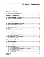
Page 13: ...p Terminal and Cable Connections 2 11 2 9 1 Setup Terminal 2 11 2 9 2 Connecting Cable 2 11 2 9 3 Connecting a Setup Terminal to the GR2000 B 2 12 2 9 4 Connecting the GR2000 B to Other Devices 2 12 2 9 5 Turning the Power Switch ON 2 13 2 10 Normal Start Up Process for the GR2000 B 2 13 2 10 1 Turning the Power OFF 2 13 Chapter 3 Basic Operations 3 1 3 1 Configuration Examples 3 1 3 2 Startup of ...

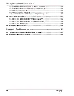
Page 14: ...t the Configuration Edit Mode Finish Editing the Configuration 3 6 3 4 Display of Operation Status 3 7 3 4 1 Display of the Operation Status Covering the Entire Router 3 7 3 4 2 Display of the Operation Status of the Built In Ethernet 3 8 3 4 3 Display of the Operation Status of the Interface Configured 3 8 3 4 4 Display of the Routing Table 3 8 3 5 More Details About Operation 3 9 Chapter 4 Troub...

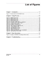
Page 15: ...00 B 2 7 Figure 2 7 Locking the Power Cable into Place 2 7 Figure 2 8 Location of Power Switch 2 8 Figure 2 9 Installation of a Memory Card 2 8 Figure 2 10 After Installation of a Memory Card 2 9 Figure 2 11 Locking a Memory Card 2 9 Figure 2 12 Unlocking a Memory Card 2 9 Figure 2 13 Removing a Memory Card 2 10 Figure 2 14 Memory Card Removed 2 10 Figure 2 15 Connecting a Setup Terminal to the GR...

Page 16: ...Hitachi Gigabit Router GR2000 B Series Quick Start Guide xvi GR2K GA 0008 Rev 1 00 This page left intentionally blank ...

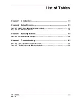
Page 17: ...e 2 1 Specifications Required for Setup Terminals 2 11 Table 2 2 Pinout for RS 232C Cable 2 11 Chapter 3 Basic Operations 3 1 Table 3 1 Details About Other Settings 3 9 Chapter 4 Troubleshooting 4 1 Table 4 1 Types of Trouble and Corrective Action 4 1 Table 4 2 Troubleshooting and Reference manuals 4 2 ...

Page 18: ...Hitachi Gigabit Router GR2000 B Series Quick Start Guide xviii GR2K GA 0008 Rev 1 00 This page left intentionally blank ...

Page 19: ...logging in setting the time configurations or excuting operational commands Chapter 4 gives information about the troubleshooting communication problems or an apparently malfunctioning GR2000 B 1 1 Documents about the GR2000 B models This manual guides you on how to operate the GR2000 B models from unpacking them to inputting the basic commands Mind that the information given here is the minimum k...

Page 20: ...onditions required for installing hardware or detailed information about operation log messages and supported MIBs or command input syntax and detailed parameters Hitachi Gigabit Router GR2000 B Series Installation Guide or if you want to know how to handle hardware Hitachi Gigabit Router GR2000 Enhanced Version Applications Guide If you want to know the configuration method and examples or detail...

Page 21: ...nstalling a Memory Card on page 2 8 2 8 Software on page 2 10 2 9 The Setup Terminal and Cable Connections on page 2 11 2 10 Normal Start Up Process for the GR2000 B on page 2 13 2 1 Check that All Necessary Components are Present Before you unpack the GR2000 B find the packing list and check the contents of the box against the list Make sure that all components are present before you begin the se...

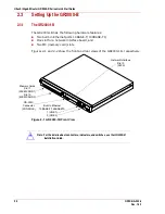
Page 22: ...slot for a network interface board and Two MC memory card slots Figures 2 1 and 2 2 show the front and rear views of the GR2000 1B respectively Figure 2 1 GR2000 1B Front View Note For the details about connectors indicators and switches see the GR2000 B Installation Guide Memory Cards Slot 1 MEM CARD 1 Slot 0 MEM CARD 0 RS 232C Connector CONSOLE Built In Ethernet 10BASE T 100BASETX 1 LINE 1 0 LIN...

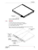
Page 23: ...ards and Two MC Memory Card slots Figure 2 3 shows the front view of the GR2000 2B with both option slots filled Figure 2 4 show the rear view of the GR2000 2B Figure 2 3 GR2000 2B Front View Power Plug with Locking Bail Power Switch Memory Cards Slot 1 MEM CARD 1 Slot 0 MEM CARD 0 RS 232C Connector CONSOLE Built In Ethernet 10BASE T 100BASETX 3 LINE 3 2 LINE 2 1 LINE 1 0 LINE 0 Network Interface ...

Page 24: ...000 B Series Quick Start Guide 2 4 GR2K GA 0008 Rev 1 00 Figure 2 4 GR2000 2B Rear View Note For the details about connectors indicators and switches see the GR2000 B Installation Guide Power Plug with Locking Bail Power Switch ...

Page 25: ...en cause a fire Secure a space of 70mm from around the ventilation slots Do not put objects weighing more than 5 kg 11 lbs on the router Otherwise you can damage the router or cause it to fall Caution When working around the router wear a wrist strap to prevent static electricity discharge Without a wrist strap the GR2000 B might be damaged due to static electricity Note Place the GR2000 B in a po...

Page 26: ...ing procedures If you want to install a GR2000 B in a rack see the GR2000 B Installation Guide 1 Place the router upside down on a flat clean surface 2 As shown in Figure 2 5 attach the rubber feet to the 1 5 mm holes 4 holes in all Figure 2 5 Attaching the Rubber Feet 3 Turn over the router and install it on a desk Note Do not attach the rubber stoppers to the router when installing it into a rac...

Page 27: ... 2 7 lock the power cable connector into place on the GR2000 B chassis Figure 2 7 Locking the Power Cable into Place DANGER To prevent the possibility of electric shock use only grounded power outlets Note When pulling a cable out of the connector follow the procedures above in reverse order ACConnector Metal bail tolock power cablein place Power cable Push down the locking metal bail toward the d...

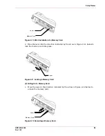
Page 28: ...g and removing a memory card from memory card slot 0 The operations for the memory card slot 1 are same as those for the memory card slot 0 1 Installing a Memory Card 1 Insert a memory card in the position shown in Figure 2 9 and Figure 2 10 below When successfully inserted the lever next to the slot will be pushed forward Figure 2 9 Installation of a Memory Card Note When inserting a memory card ...

Page 29: ...ndicated by the arrow in Figure 2 11 below to lock the memory card into place Figure 2 11 Locking a Memory Card 2 Pulling Out a Memory Card 1 Move the lever in the direction indicated by the arrow in Figure 2 12 below to unlock the memory card Figure 2 12 Unlocking a Memory Card Lever Memory Card Lever Lock Lever Memory Card ...

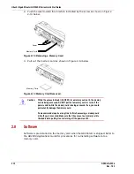
Page 30: ...ed Refer to the GR2000 Applications Guide for procedures for re installing software onto a memory card Caution While the access indicator ACCESS for a memory card is lit the memory card is being accessed DO NOT pull out a memory card or turn off the power switch while the memory card is being accessed If so you could permanently damage the memory card Some commands require a long time to finish ac...

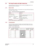
Page 31: ...t of the RS 232C cable Table 2 1 Specifications Required for Setup Terminals Category Specification Communication port RS 232C Communication software Hyperterminal utility in Windows 95 98 or other similar terminal communication software Communication settings Transfer Protocol ZMODEM Parameter 8 bits data 1 stop bit no parity Speed in bps Note 19200 9600 4800 2400 or 1200 Other features CD ROM dr...

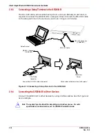
Page 32: ...gure 2 15 Connecting a Setup Terminal to the GR2000 B 2 9 4 Connecting the GR2000 B to Other Devices Connect the GR2000 B to other devices by using interface cables See the Figure 4 1 as an example Note The required type of cables differs depending on an interface you use For cable specificationa and characteristics see the GR2000 B Installation Guide RS 232C Cable RS 232C Connector CONSOLE Setup ...

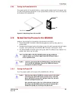
Page 33: ... then starts up normally 2 10 1 Turning the Power OFF Turn the power switch at the back of the GR2000 B to OFF 0 Note The STATUS RMP or STATUS ETHERNET indicator showing red indicates trouble For details see the Hitachi Gigabit Router GR2000 Series Enhanced Version Operations Guide Caution If a memory card is not installed the GR2000 B stops running while showing 20 in the STATUS CODE display Powe...

Page 34: ...Hitachi Gigabit Router GR2000 B Series Quick Start Guide 2 14 GR2K GA 0008 Rev 1 00 This page left intentionally blank ...

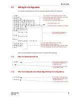
Page 35: ...n explains about the simple method of setting configurations Figure 3 1 Example of a GR2000 B Connecting to Other Devices To construct the configuration above in Figure 3 1 set the GR2000 B according to the following instructions Set IP address 192 168 1 1 for PORT 0 of the GR2000 B built in Ethernet Set IP address 192 168 2 1 for PORT 1 of the GR2000 B built in Ethernet Set IP address 192 168 2 2...

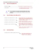
Page 36: ...t time use the show calendar command Note We strongly recommend that you set a password to secure the router You can set a password with passwd command ORJLQ RSHUDWRU OO 5LJKWV 5HVHUYHG RS ULJKW LWDFKL WG HOFRPH WR WKH 5RXWHU FRPPDQG FRPPDQG FOL Input the login user name operator Command mode is switched to the one similar to those of the routers used in general worldwide Command prompt is shown a...

Page 37: ... FORVH FRQILJ H LW H LW 5 A default route is set 6 The information configured is dispayed The information displayed as a result of the configuration 1 The system enters the administrator mode 2 The system enters the configuration edit mode 3 The configuration file is opened 4 IP address is set for the Ethernet port 7 The configuration information is saved 8 The configuration file is closed 9 The s...

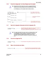
Page 38: ...RQILJ OLQH 1 HWKHUQHW FRQILJ OLQH 1 HWKHUQHW FRQILJ LS 1 FRQILJ LS 1 Set built in Ethernet Port 0 of as LAN0 with the line command The 2 0 means that the NIF number is 2 and the port number is 0 the built in Ethernet is com mensurate with the NIF number 2 Likewise set built in Ethernet port 1 as LAN1 The prompt is shown after the configuration changes Set an IP address and the subnet mask length f...

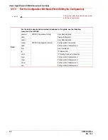
Page 39: ...e the information is saved into the operative configuration file on memory You can save the information into any preparative configuration file designated by inputting a file name FRQILJ VKRZ OLQH 1 HWKHUQHW OLQH 1 HWKHUQHW LS 1 LS 1 VWDWLF GHIDXOW JDWHZD FRQILJ The configuration information is displayed by the show command The information displayed as a result The config prompt is shown after the...

Page 40: ...000 passwd GR2000 Operations Guide User Administration date Device Information admin User Administration config GR2000 Configuration Guide Configuration Commands open Configuration Subcommand line Line Information ip IP Information static IP Routing Protocol Information save Configuration Subcommand show Configuration Subcommand close Configuration Subcommand exit Configuration Subcommand H LW The...

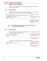
Page 41: ... 0 1 0 1 0 1 SRZHU IDQ DFWLYH QR 3 1 SRZHU DFWLYH 67 786 503 JUHHQ UP DFWLYH UP 17 51 ERRW SRZHU RQ WLPHV UHVWDUW ODPS 5 JUHHQ 50 OLJKW RII 5525 OLJKW RII 67 786 2 OLJKW RII ERDUG 38 QWHO HOHURQ 0 PHPRU 0 WHPSHUDWXUH 50 38 ERDUG QRUPDO GHJUHH 0 SULPDU VORW PF HQDEOHG XQNQRZQ 5 IRUPDW XVHG XVHU UHD GXPS UHD IUHH XVHU UHD GXPS UHD WRWDO XVHU UHD GXPS UHD 0 VHFRQGDU VORW PF GLVFRQQHFW US DFWLYH 17 51...

Page 42: ...H LQ 0ESV LQH XQXVHG D F YHUDJH RXW 0ESV YHUDJH LQ 0ESV LQH XQXVHG D F YHUDJH RXW 0ESV YHUDJH LQ 0ESV The slot number for the built in Ethernet is 2 VKRZ LS LQWHUIDFH 1 IODJV H 83 52 67 1275 56 5811 1 12 53 08 7 67 PWX LQHW EURDGFDVW 1 LQH 83 PHGLD 6 7 IXOO DXWR D F 7LPH VLQFH ODVW VWDWXV FKDQJH DVW GRZQ DW 1 IODJV H 83 52 67 1275 56 5811 1 12 53 08 7 67 PWX LQHW EURDGFDVW 1 LQH 83 PHGLD 6 7 IXOO ...

Page 43: ...he operation Configuration GR2000 Configuration Guide Setting examples related to the IP routing protocols Setting examples related to the IPv6 routing protocols Setting for network interfaces GR2000 Configuration Guide Setting examples related to the network interfaces Setting examples related to the IPv6 network interfaces Operation of the GR2000 B GR2000 Operations Guide Startup of the operatio...

Page 44: ...Hitachi Gigabit Router GR2000 B Series Quick Start Guide 3 10 GR2K GA 0008 Rev 1 00 This page left intentionally blank ...

Page 45: ...tion parameters for the software of the terminal are correctly set Regarding the communication parameters see Table 2 1 Specifications Required for Setup Terminals on page 2 11 The router stops running while showing 20 for the STATUS CODE If a memory card is not installed into the device Turn off power to the router and install a memory card according to the instructions of section 2 7 Installing ...

Page 46: ...Details About Troubleshooting See the manuals listed in the Table 4 2 for detailed troubleshooting Table 4 2 Troubleshooting and Reference manuals Item Reference manuals Reference sections Trouble of every kind GR2000 Operations Guide Troubleshooting Details for the operation log Log messages ...

Page 47: ...Troubleshooting GR2K GA 0008 4 3 Rev 1 00 This page left intentionally blank ...

Page 48: ...uter GR2000 B Series Quick Start Guide Part No GR2K GA 0008 Rev 1 00 Copyright 2002 Hitachi America Ltd All rights reserved Printed in the U S A Hitachi America Ltd 2000 Sierra Point Parkway Brisbane CA 94005 1835 U S A ...

Reviews: