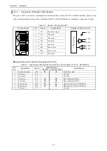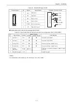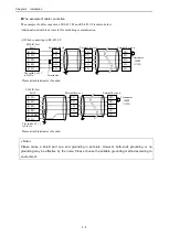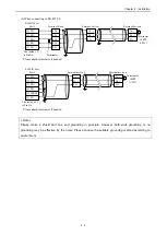
Chapter 5 Control of EH-SIO
5 - 10
5.2.2
Detail of input register
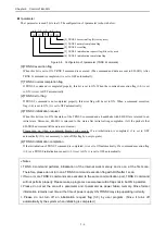
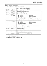
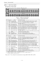
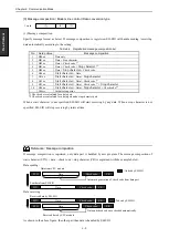
Configuration of status register
The status register consists of 16 bits. A meaning is different for each bit.
WX r u s 0
Bit
15
14
13
12
11
10
9
8
7
6
5
4
3
2
1
0
Abbreviation
XCNT1 XHS1 XIC1
--
XRS1 XMDE XCDE1 XDTE1 CD1
CS1
DR1
--
TII1
PTE1 OBE1 IBE1
WX r u s 1
Bit
31
30
29
28
27
26
25
24
23
22
21
20
19
18
17
16
Abbreviation
XCNT2 XHS2 XIC2
--
XRS2 XMDE XCDE2 XDTE2 CD2
CS2
DR2
IFS
TII2
PTE2 OBE2 IBE2
Figure 5.9 Configuration of status register
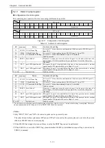
Table 5.2 Contents of status register
Bit
Abbreviation
Name
Contents of each flag
15
XCNT1 X-CoNTinue flag
It is set to "1" while having transmitted the data of the port 1 to CPU.
14
XHS1 X-HandShake flag
It is set to "1" when ready for sending the data of the port 1 to CPU.
13
XIC1
X-Initial Complete flag It is set to "1" if initial setting of the port 1 is completed.
12
--
Undefined. always "0".
11
XRS1*
3
X-Receiving Started
It is set to "1" when more than 1 byte of data is received at the port 1.
10
XMDE X-MoDuleError flag
It is set to "1" when a serious failure error occurs in EH-SIO.
9
XCDE1 X-CommanD Error flag It is set to "1" when the error of a warning level occurs in the port 1.
8
XDTE1 X-DaTa Error flag
It is set to "1" when an error occurs to the transmission data in the port 1.
7
CD1
port1 CD signal status
The state of CD signal of a port 1. It is set to "1" at the time of High.
6
CS1
port1 CS signal status
The state of CS signal of a port 1. It is set to "1" at the time of High.
5
DR1
port1 DR signal status
The state of DR signal of a port 1. It is set to "1" at the time of High.
4
--
Undefined. always "0".
3
TII1
port1 Trns Instruction
Invalid
It is set to "1" when a port 1 is in the state of the TRNS command non-effect
(setup the dedicated procedure mode*
1
).
2
PTE1
PorT1 Error
It is set to "1" when a port 1 has an error.
1
OBE1 Out Buffer 1 Empty
It is set to "1" when the send buffer for port 1 is empty.
0
IBE1
In Buffer 1 Exist
It is set to "1" when data is in the receive buffer for the port 1.
Bit
Abbreviation
Name
Contents of each flag
31
XCNT2 X-CoNTinue flag
It is set to "1" while having transmitted the data of the port 2 to CPU.
30
XHS2 X-HandShake flag
It is set to "1" when ready for sending the data of the port 2 to CPU.
29
XIC2
X-Initial Complete flag It is set to "1" if initial setting of a port 2 is completed.
28
--
Undefined. always "0".
27
XRS2*
3
X-Receiving Started
It is set to "1" when more than 1 byte of data is received at the port 2.
26
XMDE X-MoDuleError flag
It is set to "1" when a serious failure error occurs in EH-SIO.
25
XCDE2 X-CommanD Error flag It is set to "1" when the error of a warning level occurs in the port 2.
24
XDTE2 X-DaTa Error flag
It is set to "1" when an error occurs to the transmission data in the port 2.
23
CD2*
2
port2 CD signal status
The state of CD signal of a port 2. It is set to "1" at the time of High.
22
CS2*
2
port2 CS signal status
The state of CS signal of a port 2. It is set to "1" at the time of High.
21
DR2*
2
port2 DR signal status
The state of DR signal of a port 2. It is set to "1" at the time of High.
20
IFS
InterFace Select
The communication I/F of Port2. It is set to "1" at the time of RS-422/485.
It is set to "0" at the time of RS-232C.
19
TII2
port2 Trns Instruction
Invalid
It is set to "1" when a port 2 is in the state of the TRNS command non-effect
(setup the dedicated procedure mode *
1
).
18
PTE2
PorT2 Error
It is set to "1" when a port 2 has an error.
17
OBE2 Out Buffer 2 Empty
It is set to "1" when the send buffer for port 2 is empty.
16
IBE2
In Buffer 2 Exist
It is set to "1" when data is in the receive buffer for port 2.
*1 Modbus slave mode, Hi-Protocol mode, Simple data link mode
*2 When RS-422 and 485 are used for communication I/F of a port 2, undefined. (always "1")
*3 This flag is added from software version 3.0.
Please refer to "7.2 Error indication" about the details of error flags (XMDE, XCDE, XDTE, and PTE).
Summary of Contents for EH-150 Series
Page 2: ......
Page 10: ...M E M O ...
Page 30: ...Chapter 4 Installation 4 10 M E M O ...
Page 156: ...Chapter 7 System setup 7 12 M E M O ...
Page 164: ...Chapter 8 Daily and Periodic Inspection 8 8 M E M O ...

