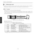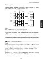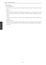
Chapter 6 Communication Mode
6 - 54
Mod
b
u
s S
lav
e
6.4.3
Initial setting
EH-SIO becomes idle status (waiting to be initial setting by CPU module) after power ON.
In modbus slave mode, EH-SIO works while CPU module in stop mode. Communication mode is cleared by reset
button or rebooting the power.
« Note »
EH-SIO will not receive any operation command from CPU module or external device before initial setting.
Parameters for initial setting
Table 6.15 Parameter table for initial setting
No.
Parameter
Description
1
Communication mode
Set Modbus slave mode (H0011)
2
Modbus mode
Select ASCII mode or RTU mode
Note : Only RTU mode is available in software ver. 1.0
3
Node number
Set node number (station number)
4
Waiting time
Waiting time from receiving a query to sending response.
5
I/O mapping information
(Bit)
Please specify, when you assign a coil (bit data) to I/O other than a default.
* The I/O mapping function has not been supported in software ver. 1.0.
Set H0000 in software ver. 1.0
6
I/O mapping information
(Word)
Please specify, when you assign a register (word data) to I/O other than a default.
* The I/O mapping function has not been supported in software ver. 1.0.
Set H0000 in software ver. 1.0
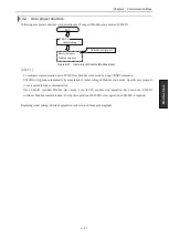
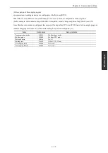
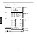
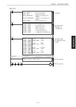
Parameter of TRNS 9 command for initial setting
Command number of initial setting in s+7 is H0000
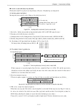
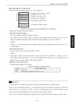
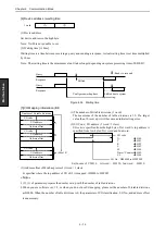
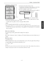
Be sure to set parameters in the sending data area (s+9 to s+A) according to the next page, and be sure to set
dummy parameter in the receiving data area (s+B to s+D) although nothing is stored in the configured address area.
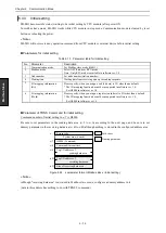
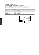
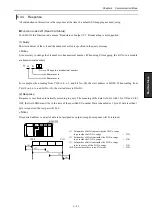
Figure 6.52 s parameter format (Modbus slave / Initial setting)
« Note »
Although "receiving data area" is not used in Modbus slave mode, configure a dummy address in it.
(data in this address has nothing to do with TRNS 9 command.)
Size of receiving data area
Top I/O address of
receiving data area
Return code
H0000 (Command)
Command timeout time
Top I/O address of
sending data area
s
s+7
s+8
s+9
s+B
s+D
System area (6 word)
Set by user
Dummy parameter
Summary of Contents for EH-150 Series
Page 2: ......
Page 10: ...M E M O ...
Page 30: ...Chapter 4 Installation 4 10 M E M O ...
Page 156: ...Chapter 7 System setup 7 12 M E M O ...
Page 164: ...Chapter 8 Daily and Periodic Inspection 8 8 M E M O ...

