


2 - 8
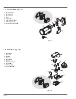
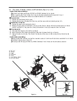
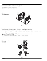
4.2
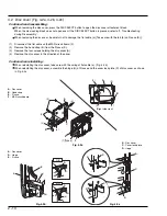
4.1
4.1
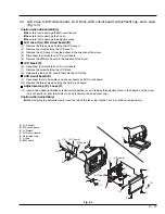
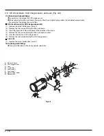
4.4
4.8
4.11
4.8
4.8
4.8
4.4
4.4
4.4
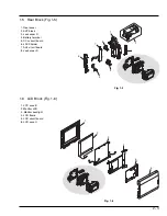
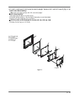
4.5
4.5
4.5
4.6
4.9
4.4
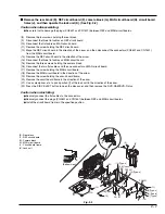
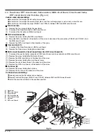
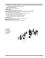
4.3
4.3
4.10
4.7
4.3
4.3
4.11
4.8
4.3
4.7
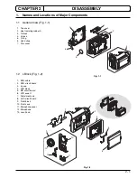
Component
name
Item
no.
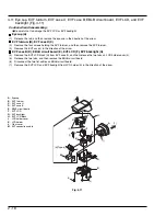
Top cover
Eyecup
LCD case U
MR circuit
board
Lens hood
Adjustment
cap
R block
L block
Front block
LCD block
Rear block
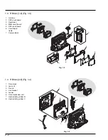
LCD circuit
board
LCD frame
Monitor
backligh
Monitor LCD
LCD case B
Microphone
cover
Microphone
Front case
Disc cover
AUD circuit
board
REF circuit
board
EVF block
Battery
terminal
Jack holder
Jack cover S
AVJ circuit
board
DCJ circuit
board
Link bracket
L case
Camera block
EVF fulcrum
EVF case U
EVF case B
EBLB circuit
board
EVF LCD
EVF backlight
Jack cover R
Drive block
MAN circuit
board
Circuit board
frame
DRF circuit
board
Hot shoe
SE circuit
board
CCD image
sensor
Lens
Rear cover
Lock unit
R case
Loader
Drive
mechanism
unit
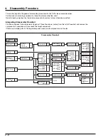
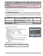
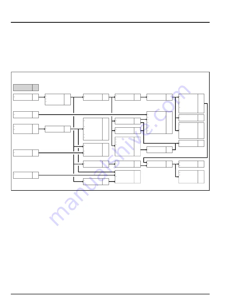
4.
Disassembly Procedure
This section explains the general disassembly procedure for this DVD video camera/recorder.
For the order of removing components, follow the disassembly flow chart.
Reinstall each component by the reverse procedure to removal unless otherwise specified.
Interpreting Disassembly Flowchart
Find the component to be removed in flowchart: Trace the arrows (routes) from the left of flowchart, and remove the
components in sequence until you reach the target component.
If there are multiple paths to the target component, remove all components on all routes.
Disassembly Flowchart