background image

5 - 30

Disassembly and Reassembly > EEPROM Data Backup and Write
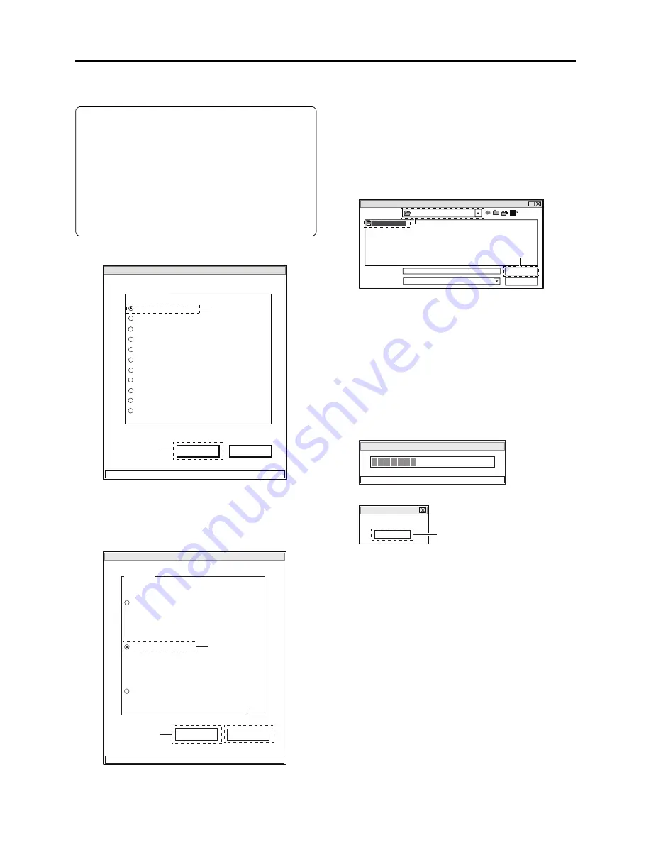
5-4-2 Write Method

Restrictions:

Never write data of any other product.
The EEPROM data includes adjustment 
values, etc. that are peculiar to that product: 
It is different for each product even if the 
model is the same.
If you write the data of another product by 
mistake, rewrite the correct data.

1) Choose DATA INITIALIZE.
2) Click the EXECUTE button.

3) Choose Backup Data Write.
4) Click the EXECUTE button on DATA 

INITIALIZE MENU screen to proceed with 
the WRITE FILE SELECT screen.

5) Select the folder and 

fi

 le in which the data 

has previously been backed up.
This section refers to the folder and 

fi

 le as 

“EEP” and “backup.eep” for explanation.

6) Click the OPEN button to start writing.

The progress status can be con

fi

 rmed using 

the PROGRESS STATUS dialog.

7) Click the OK button in dialog to restore the 

DATA INITIALIZE MENU screen.

8) Click the RETURN button on DATA 

INITIALIZE MENU screen to restore the 
ADJUST MENU screen, and then perform 
adjustment according to “6-3-2 List of 
Adjustments Needed After Replacing Major 
Components”.

ADJUST MENU screen

MANUAL ADJUSTMENT PROGRAM for SERVICE STATION

MODEL NAME: 

××××

DATA INITIALIZE

EXECUTE

RETURN

CONNECTION

ADJUST MENU

SAMPLING PULSE

AUTO IRIS CONTROL

MATRIX

CHROMA GAIN

AUTO FUCUS

SPOT NOISE

LCD

VIDEO LEVEL

BURST LEVEL

LINEARITY

2

1

DATA INITIALIZE MENU screen

Data Initialize

Initial Data Write

EXECUTE

RETURN

CONNECTION

FILE MENU

Original Data Backup

Backup Data Write

4

3

8

 WRITE FILE SELECT screen

?

Look in (T):

File name (N):

File of type (T):

backup.eep

.eep

*

Open

Cancel

EEP

backup.eep

5

6

PROGRESS STATUS dialog

DATA INITIALIZE

PLEASE WAIT A MOMENT

INITIALIZATION FINISHED dialog

FINISHED

FINISHED WRITING DATA

OK

7

Summary of Contents for DZ-HS300A

Page 1: ...R IMPROVEMENT DVD VIDEO CAMERA RECORDER TK No 0612E DZ HS303A DZ HS303A K DZ HS300A DZ HS300A K DO NOT RESELL OR DIVERT IMPROPERLY 3 3 November 2006 Change 2 1 17 08 Added PWB Part Numbers to Exploded View Page 7 2 Version 0612E 2 Updated 01 17 2008 PARTS LIST ADDED ...

Page 2: ... codes and troubleshooting 4 15 4 3 4 DVD Load Check Flowchart 4 17 4 3 5 Cleaning DVD and optical pickup 4 18 4 4 Checking Versions of Firmware and Updating 4 19 4 4 1 Checking firmware versions 4 20 4 4 2 Updating firmware 4 21 4 5 Trouble Diagnosis 4 23 4 5 1 Trouble diagnosis flowchart 4 24 4 5 2 Reassembly to enable service position 4 36 4 6 Procedure for Removing DVD from Faulty DVD Video Ca...

Page 3: ... Copying or Deleting Adjustment Software 6 7 6 1 7 Starting and Terminating Reference Data Creation Software 6 7 6 1 8 Creating Reference Data 6 10 6 2 Setups for Adjustment 6 12 6 2 1 List of Jigs and Tools for Adjustment 6 12 6 2 2 Test Equipment Power Supply and Charts for Adjustment 6 12 6 2 3 Connections for Adjustment 6 12 6 2 4 Settings for Adjustment 6 14 6 2 5 Starting and Terminating Adj...

Page 4: ...6 S 17 LENS DRIVE MAN S 17 S 18 REGULATOR MAN S 18 S 19 IC Block 1 2 S 19 S 20 IC Block 2 2 S 20 C Circuit Board Diagrams C 1 C 1 GSL 3M For HS303A C 1 C 2 GSL L For HS300A C 2 C 3 FRT H L C 3 C 4 AVJ H L C 4 C 5 LMF H L C 5 C 6 SHE H For HS303A C 6 C 7 MAN C 7 B Block Diagram B 1 B 1 OVERALL B 1 iii ...

Page 5: ...ACHI Service Manual A subscription to or additional copies for HITACHI Service Manual may be obtained at a nominal charge from HITACHI SALES CORPORATION PRODUCT SAFETY NOTICE CAUTION There is a high voltage section inside the DVD video camera recorder When repairing or inspecting it take great care to prevent electric shock Use an isolating transformer wear gloves etc CLASS 1 LASERPRODUCT CAUTION ...

Page 6: ...observe the following cautions 1 Do not subject optical pickups to any severe vibrations or impact during movement installation or disassembly 2 When performing repair work do not perform disassembly any further than that described in this manual 3 Never turn the semi variable resistors for adjustment in optical pickup or DVD drive 4 NEVER look into the objective lens in optical pickup or directly...

Page 7: ...move the power supply battery or AC adapter charger during recording playback editing or dubbing Doing so could damage the data on HDD Always set the power switch to OFF before removing the power supply 2 Do not subject the DVD video camera recorder to any vibration as far as possible during recording playback editing or dubbing Also never strike the DVD video camera recorder The head will hit the...

Page 8: ...ollowing before soldering Caution ALWAYS wear protective goggles during soldering so that no solder smoke or scattered solder enters the eye Lead free solder may scatter at high temperatures of 600 C 1 Identification of circuit boards that use lead free solder is stamped or noted with pattern letter on circuit boards that use lead free solder 2 Characteristics of lead free solder The components of...

Page 9: ... 1 Before using lead based solder remove the lead free solder completely from the point to be soldered 2 For additional soldering for repair set the soldering iron tip temperature for lead free solder mix lead based solder and lead free solder sufficiently Do not perform any repair using the bare soldering iron tip without adding solder since it will cause secondary failure due to lack of strength...

Page 10: ...des A B in circuit board diagrams 1 Board with pattern on one side only and parts on both sides Side A Shows discrete parts Side B Shows leadless parts viewed from the pattern side 2 Board with patterns and parts on both sides Sides A and B are identified without any predetermined rules Parts Indication in list Regular indication Resistor KOHM k Capacitor UF μF PF pF Coil UH μH MH mH Item Indicati...

Page 11: ...D875LA D975LA D875LA 2 If there is no difference in models going to different destinations the indication of destination is omitted Example When indicating DZ MV350E AU and DZ MV350E SW DZ MV350E 5 Differences in parts between schematic and circuit board diagrams If some parts are different between models asterisks are attached to the circuit numbers Check the parts difference tables in diagrams o...

Page 12: ...303A HS300A DVD video camera recorder incorporates an 8 GB 1 inch HDD Since the DZ HS303A HS300A are also compatible with various DVDs DVD RAM DVD R DVD RW RW movies can be not only recorded on DVD or HDD but a movie recorded on HDD can also be dubbed to a DVD The DZ HS303A uses a CCD image sensor of 3 310 000 total pixels High quality stills can also be recorded on an SD memory card stills can be...

Page 13: ...ovided LMF L Circuit Board Not provided Component replacement MAN Circuit Board Component replacement SDL Circuit Board Circuit board replacement SHE H Circuit Board Component replacement Not provided Same as on left General Description Overview 2 1 1 Servicing method Refer to the following table and perform the designated appropriate servicing Any changes that occur in the service method will be ...

Page 14: ...also displayed in wide screen mode Capturing still During movie playback a desired scene can be recorded on SD memory card as a still 2 3 Specifications General Description Features Specifications Information The DZ HS303A HS300A cannot record any stills on a DVD RAM and HDD Record stills only on an SD memory card Item Specifications CCD Image Sensor DZ HS303A 1 3 inch interlaced DZ HS300A 1 6 inc...

Page 15: ... Conforming to DVD video recording DVD VR format Sound Dolby Digital DVD RW VF mode DVD R Movie Conforming to DVD video format Sound Dolby Digital RW Movie RW video format Sound Dolby Digital Card Still Conforming to JPEG DZ HS303A 2 016 1 512 pixels DZ HS300A 640 480 pixels Audio playback format MPEG Audio layer 2 linear PCM Dolby Digital Recordable disc 8 cm DVD RAM disc conforming to DVD RAM Ve...

Page 16: ...tion Specifications Item Specifications Storage temperature 4 140ºF 20 60ºC Weight without battery and disc DZ HS303A Approx 485 g DZ HS300A Approx 435 g Total weight when recording DZ HS303A Approx 560g DZ HS300A Approx 490 g Provided accessories AC adapter charger DZ ACS3 Battery DZ HS303A DZ BP14S DZ HS300A DZ BP07PW AV S input output cable DZ HS300A is provided with AV S output cable Infrared ...

Page 17: ...When Low Light mode is selected 16 9 squeeze record mode Provided Except for DVD RW VF mode DVD R RW using STD mode Viewfinder 0 2 inch color equivalent to approx 200 000 pixels with 16 9 mode LCD monitor 16 9 2 7 inch color TFT approx 120 000 pixels Sleep Restart button Provided Finalize button Provided CCD image sensor DZ HS303A 1 3 inch interlaced DZ GX3300A DZ HS300A 1 6 inch interlaced DZ BX3...

Page 18: ...Audio layer 2 Linear PCM LPCM Maximum number of recordable Stills DVD RAM FINE Not record DZ GX3300A Approx 650 DZ BX37A Approx 999 SD Memory cord 32MB FINE DZ HS303A Approx 18 DZ GX3300A DZ HS300A Approx 180 DZ BX37A NORM DZ HS303A Approx 24 DZ GX3300A DZ HS300A Approx 240 DZ BX37A ECO DZ HS303A Approx 37 DZ GX3300A DZ HS300A Approx 370 DZ BX37A Number of pixels for JPEG Still during camera recor...

Page 19: ...vided DZ BP14S 7 2V 1360mA DZ GX3300A provided DZ HS300A provided DZ DP07PW 1 7 2V 680mA DZ BX37A Optional DZ BP14SW 7 2V 1360mA DZ BP7SW 1 7 2V 680mA Optional Infrared remote control DZ RM4W Battery CR2032 1 AV input output cable or AV output cable Pin 8 type With Composite video Audio L Audio R Provided software For Windows 2 ImageMixer 3 For Macintosh 3 Pixe VRF Browser EX ImageMixer VCD DVD2 P...

Page 20: ...insert a DVD R not finalized into a DVD recorder etc 3 Inserting it may make the DVD R unusable 2 DVD R recorded or edited on other Hitachi DVD video camera recorders 2 The DVD R can be played back on DZ HS303A HS300A 4 without being finalized However be sure not to record or finalize the DVD R using DZ HS303A HS300A Doing so will make the DVD R unusable 2 Only for models that conform to DVD R See...

Page 21: ...ver be sure not to record or finalize the DVD RW using DZ HS303A HS300A Doing so will make the DVD RW unusable 4 Loading a DVD R DVD RW VF mode will automatically start the Disc Navigation function 5 Only for models that conform to DVD RW See Table 2 5 2 List of Compatible Recording Media for the models that conform 6 Except for DVD recorders etc whose instruction manuals state that This model can...

Page 22: ...30A MV200A Cartridge caddy case needed N N DZ MV100A N Table 2 5 2 List of Compatible Recording Media General Description Compatibility of Recorded DVD and Corresponding Recording Media Note 1 Do not use a DVD formatted on a device other than DZ HS303A HS300A Such a DVD may be recordable but it cannot be played back 2 Do not insert a DVD not finalized into other device except Hitachi DVD recorders...

Page 23: ... THE 6 VIDEO CAMERA RECORDER THIS RECEIVER WILL RECEIVE THE INFRARED SIGNAL PTICAL ZOOM LENS FOR 3 ONLY PTICAL ZOOM LENS FOR 3 ONLY ENS HOOD LWAYS REMOVE THIS LENS HOOD WHEN USING THE OPTIONAL TELE CONVERSION OR WIDE CONVERSION LENS OOM LEVER 4O ADJUST THE ZOOM OR VOLUME CCESSORY SHOE FOR 3 ONLY 4HE OPTIONAL VIDEO FLASH CAN BE ATTACHED HERE 3EE THE INSTRUCTION MANUAL OF DEVICE TO BE ATTACHED FOR D...

Page 24: ...ESSED WRITE ORREAD OR THE 6 VIDEO CAMERA RECORDER IS CONNECTED TO A 0 0 4 3 4 BUTTON 3 4 BUTTON 0RESS DOWN AND RELEASE THIS BUTTON TO OPEN THE COVER OF 6 INSERTION BLOCK 6 INSERTION BLOCK 44 29 4 BUTTON 0RESS THIS BUTTON WHEN REMOVING THE BATTERY ATTERY ATTACHMENT PLATFORM 2ECORD BUTTON 2 SWITCH T IS RECOMMENDED THAT YOU SET THE SWITCH TO TO THE UPPER POSITION TO PREVENT THE POWER SWITCH IN THE h ...

Page 25: ...OM THE FACTORY 30 9 3CREEN DISPLAY BUTTON 0RESS THIS BUTTON TO DISPLAY THE DETAILS OF IMAGE BEING PLAYED BACK OR CAMERA SETTING STATUS OR SWITCH THE DISPLAY OFF 2 33 INDICATOR 15 5 BUTTON 4O DISPLAY ONLY THE FUNCTIONS THAT YOU FREQUENTLY USE SIMPLE MENUS BUTTON 0RESS THIS BUTTON TO FINALISE THE RECORDED 6 27 6 2 27 ARD INSERTION BLOCK BACKLIGHT COMPENSATION BUTTON 0RESS THIS BUTTON WHEN SUBJECT IS...

Page 26: ...ERSE SEARCH BUTTON 4 BUTTON 3 6 4 BUTTON 30 9 BUTTON 4 BUTTON 4 BUTTON 7 BUTTON 2EVERSE SKIP BUTTON ORWARD SEARCH BUTTON 0LAY PAUSE BUTTON 3TOP BUTTON ORWARD SKIP BUTTON 4HE BUTTONS ON REMOTE CONTROL WILL FUNCTION THE SAME AS THOSE ON 6 VIDEO CAMERA RECORDER 2 0 4 4 5 3 4 4 3 6 4 30 9 ...

Page 27: ...ONTROL MODEL 2 7 OR 3 ONLY ITHIUM BATTERY MODEL 2 OR 3 ONLY 4O POWER THE REMOTE CONTROL 6 3 INPUT OUTPUT CABLE OR 3 ONLY 6 3 OUTPUT CABLE OR 3 ONLY 3HOULDER STRAP ENS CAP AND LENS CAP STRING 3OFTWARE 2 0 CONNECTION CABLE ISC CLEANING CLOTH 7 2 EEP THIS BATTERY AWAY FROM CHILDREN F SWALLOWED CONSULT A PHYSICIAN IMMEDIATELY FOR EMERGENCY TREATMENT Accessories ...

Page 28: ... RW One type of DVD standard disc to which writing up to 1000 times is possible DVD Video One type of DVD standard disc on which high quality video and audio can be recorded DVD Video Format Video recording playback standard that applies to DVD Video DVD R and DVD RW DVD Video Video recording playback standard that applies to DVD RAM and DVD RW This Recording Format allows versatile editing functi...

Page 29: ... Secure MultiMediaCard Secure Also referred to as SecureMMC This compact memory card has multimedia card MultiMediaCard specifications to which an advanced copyright protection function is added Software disc Protect This function writes the protect information to DVD RAM disc to prevent accidental erasure Software Disc Protect is included in DVD RAM disc specifications defined by DVD Forum STN LC...

Page 30: ...Incorporates the AV output PC connection and external microphone terminals H is for DZ HS303A and L for DZ HS300A f FRT H L circuit board Incorporates the white balance WB sensor remote infrared receiver IR sensor etc The FRT H circuit board in DZ HS303A also has a flash circuit H is for DZ HS303A and L for DZ HS300A g GSL 3M L circuit board This circuit board connects the CCD image sensor to MAN ...

Page 31: ...oard in L case has a card slot It also relays the LCD and MAN circuit boards Item Specification Interface ATA on MMC Storage capacity 8 GB Number of disks 1 Disc rotation speed 3600 rpm Average seek time read 12 ms Average rotation wait time 8 33 ms Surface recording density max 163 Mb mm2 105Gb in2 Data transfer speed during media recording playback 68 131 Mb s Interface transfer speed 26 MB s Da...

Page 32: ...nctions setup menu if you plan to record in a weightless condition for an extended time The HDD Protection Off setting will automatically return to On when the DVD video camera recorder is powered next time 3 2 3 Dubbing Button Used to dub the movies sounds recorded on the HDD to a DVD by the following procedure Set the power switch to OFF or DVD press the DISC EJECT button and then load a recorda...

Page 33: ...de OK OK OK OK DVD RW VF mode NG NG NG OK DVD R NG NG NG OK RW OK OK NG OK Information 1 Dubbing from DVD to HDD between HDD and SD memory card or between DVD and SD memory card is not possible 2 Use the AC adapter charger to power the DVD video camera recorder during dubbing The DVD video camera recorder is designed so that dubbing is not possible when a battery is connected since turning power o...

Page 34: ...on received product in the Memo columns referring to Table 4 7 1 List of items to be reset These notes will be necessary not only for reset but for checking any defects that occur under the particular setting conditions Troubleshooting 1 Messages and error codes will appear on LCD monitor or in viewfinder Fig 4 1 1 Check phenomenon No message appears 1 Message appears 1 Display of Error Codes and ...

Page 35: ...iple scenes is possible Stop trying to combine scenes or create a play list containing the scenes to be combined and combine them on the play list Cannot combine scene of multiple programs Create Playlist first and then combine scenes Appears when combining the scenes in different programs was attempted When combining those scenes first create a play list and then combine the scenes on it Cannot c...

Page 36: ...stipulate that the thumbnail of still cannot be changed Select a movie to change the thumbnail Cannot select any more scenes Appears when the number of scenes selected on card has exceeded the upper limit of 999 scenes Release the selection of unnecessary scenes CANNOT SLEEP MODE Appears when the DVD video camera recorder cannot enter the SLEEP mode because it is set to the recording pause status ...

Page 37: ...engaged release it If HDD protection has not been engaged replace the HDD Control Information Error Also appears when reading or writing from to recorded file cannot be performed because the DVD is dirty Refer to 4 3 5 Cleaning DVD and optical pickup and clean the DVD Or replace the DVD Appears when mismatch between recorded scene and scene information occurs Such a mismatch occurs when editing is...

Page 38: ...g normal opera tion Operate the DVD video camera re corder after the message disappears If the message does not disappear see 4 5 Trouble Diagnosis DVD error has occurred Finalizing is not complete Appears when the DVD could not be finalized because it was dirty Refer to 4 3 5 Cleaning DVD and optical pickup and clean the DVD Or replace the DVD Appears if accident such as power off has occurred du...

Page 39: ...unfinalizing Set the power switch to OFF reattach the AC adapter charger set the power switch to DVD and then unfinalize the disc again Or press the DISC EJECT button to remove the DVD reload it and then unfinalize it again If no recovery is made even when the DVD is cleaned or unfinalized again the DVD may be defective Replace the DVD DVD error has occurred Also appears when reading or writing fr...

Page 40: ...ose YES VR Mode VF Mode and designate it Displayed only when DVD RW is used DVD format Select record format VR mode VF mode Appears when reading or writing from to recorded file cannot be performed because the DVD is dirty Refer to 4 3 5 Cleaning DVD and optical pickup and clean the DVD Or replace the DVD May appear when a DVD formatted and recorded on a device other than DVD video camera recorder...

Page 41: ...t recording will be held on the DVD RW VF mode DVD R Stop trying to change the video quality or wide mode or replace the DVD DVD RW VF Video mode and 16 9 mode cannot be cheanged DVD RAM Finalize is not required Appears when the FINALIZE button was pressed with a DVD RAM used A DVD RAM does not need to be finalized Wait until the message disappears END OF DVD Appears if the DVD recordable capacity...

Page 42: ...en initializing deleting all recorded data and then execute HDD error has occurred Formating is not complete Appears when formatting of HDD was not completed normally or it was interrupted Execute system reset set the power switch to OFF remove the power supply use a fine tipped pen to hold down the RESET button for a few seconds and then format the HDD again HDD error has occurred Restart Appears...

Page 43: ...amera recorder may be faulty Refer to 4 5 Trouble Diagnosis No more scenes Play List was deleted Appears during user operation all recorded scenes have been deleted and cleared The specifications stipulate that a play list with no scene on it cannot be held If all registered scenes have been deleted the play list will also be deleted Operate the DVD video camera recorder after the message disappea...

Page 44: ...L system Please replace DVD Appears when a disc recorded in the PAL system was loaded This DVD video camera recorder is exclusively for the NTSC system and does not comply with the PAL system Use a disc recorded in the NTSC system The scene from which Video mode Wide mode differs cannot combine Appears if an attempt is made to combine scenes with different movie qualities or with different wide mo...

Page 45: ...he DVD loaded remove the battery and then connect the AC adapter charger Finalize the DVD again Use AC adapter charger Turn off power Appears if a battery is used when repairing video files The specifications state that video files can be repaired only when the AC adapter charger powers the DVD video camera recorder Set the power switch to OFF with the DVD loaded remove the battery and then connec...

Page 46: ...e disc left loaded after camera recording choose repair b If recording and playback are possible with another disc which is free from condensation or dirt choose repair c The HDD can be repaired when a battery is connected except when the remaining level indicator blinks but be sure to connect the AC adapter charger when repairing DVD The specifications state that DVD cannot be repaired when the D...

Page 47: ...isplay method 1 Use the battery or AC adapter charger to power the DVD video camera recorder 2 Set the power switch to HDD If a DVD is loaded this function can also be executed with the power placed in the DVD position Then operate the DVD video camera recorder while watching the LCD monitor or viewfinder 3 Press the DISC NAVIGATION button to display the thumbnail screen 4 Display the error code s...

Page 48: ...eshooting Troubleshooting Display of Error Codes and Troubleshooting Error code Contents of problem Troubleshooting 0200 Optical pickup failed to move Refer to 4 3 4 DVD load check flowchart 0280 0400 Recognition of DVD failed 0401 Optical pickup was faulty Replace the DVD drive unit 040D No DVD Load a DVD 1001 DVD RW RW was not formatted 1 Format the DVD RW RW 1100 Reading data from DVD failed Re...

Page 49: ... DVD referring to 4 6 Procedure for Removing DVD from Faulty DVD Video Camera Recorder and then refer to 4 5 Trouble Diagnosis A080 Reading signal from disc failed due to condensation or dirt on DVD With the DVD loaded set the power switch to OFF and then leave the DVD video camera recorder in a dry place until condensation disappears for at least 1 2 hours Clean the optical pickup referring to 4 ...

Page 50: ...o Yes No Yes Check the DVD loaded status Is a single sided DVD used Is DVD loaded with the recording surface facing the optical pickup Load the DVD with the recording surface facing the optical pickup Is DVD properly attached to the turntable Push the DVD onto the turntable until a click is heard Is there a foreign object in the vicinity of turntable Remove the foreign object Is DVD usable on the ...

Page 51: ...eaners and cleaning cloths generally available are also usable a KS2424 X00 Toraysee cleaning cloth only produced by Toray b LF K200DCJ1 DVD RAM PD disc cleaner cleaning cloth and cleaning liquid produced by Panasonic c OC CS MO disc cleaner cleaning cloth and cleaning liquid produced by Hitachi Maxell 2 Cleaning optical pickup Note Do not clean the optical pickup needlessly The optical pickup is ...

Page 52: ...e and Updating The DVD video camera recorder stores in flash memory the five types of firmware program shown in Table 4 4 1 These firmware programs can be updated whenever necessary to improve performance Check to see whether any defects in the DVD video camera recorder can be eliminated by updating any firmware programs If improvement is likely update them Information The information on how to up...

Page 53: ...ethod 1 If no DVD is loaded press the STOP CANCEL button to restore the normal screen If a DVD is loaded press the STOP CANCEL button to restore the thumbnail screen To restore the normal screen also press the STOP CANCEL button or DISC NAVIGATION button 3 Details of information version screens Table 4 4 2 Detail Version Screens Troubleshooting Checking Versions of Firmware and Updating Fig 4 4 1 ...

Page 54: ...s and operability of DVD video camera recorder Caution There are three types of camera microprocessor firmware for DZ HS303A HS300A depending on the number of pixels of CCD image sensor Be sure to acquire the appropriate data before updating the corresponding model and then create a disc card for updating If a disc card for updating a model other than that to be serviced is inserted an mismatch sc...

Page 55: ...Loader Camera Update Screen Updating camera Firmware Update Firmware Update Firmware Update Do not turn off power Do not turn off power Firmware Update Firmware Update Updating drive Core Please wait about 1 minutes Do not turn off power Firmware Update Drive Core Update Screen Firmware Update Firmware Update Firmware Update Unmatched Screen This disc is not an update disc for this camera Firmware...

Page 56: ...s troubleshooting for the symptoms shown below Power supply system Power does not turn on HDD system HDD does not operate Message HDD ACCESS does not disappear Disc system Recognition of DVD does not start even if a normal DVD is loaded Message NO DVD appears even if a normal DVD is loaded Message DVD ACCESS does not disappear even if a normal DVD is loaded Message Write protected Check DVD appear...

Page 57: ...ssembly to enable service position No improvement Yes No Yes No Yes No Yes No Power does not turn on Set to service position A and connect the AC adapter chager TL7040 0V Power switch faulty Replace the rear case Is fuse F7000 blown Replace the DVD drive unit and F7000 Set the power switch to DVD position and return to OFF position Reset the DVD position Replace the DVD drive unit and F7003 Replac...

Page 58: ...6 CIRCUIT BOARD CONNECTED 2EPLACE THE CIRCUIT BOARD 3 CIRCUIT FAULTY 6 OR 24 CIRCUIT FAULTY RE ANY OF FUSES AND BLOWN 2EPLACE THE 6 DRIVE UNIT RE ANY OF FUSES AND BLOWN 2EPLACE THE CIRCUIT BOARD O NOT CONNECT THE 6 CIRCUIT BOARD FTER REPLACING THE FUSE CONNECT THE 3 CIRCUIT BOARD AND SUPPLY POWER RE ANY OF FUSES AND BLOWN ...

Page 59: ... the HDD unit Replace the HDD unit HDD does not operate Message HDD ACCESS does not disappear Information With the DZ HS303A HS300A the HDD unit is set to master and the DVD drive unit is set to slave Therefore if the HDD unit is electrically faulty the DZ HS303A HS300A may not recognize the DVD drive unit and the DVD drive unit may not operate ...

Page 60: ...rcuit board Lead wire soldered or not R7036 MAN A 3E Need Remove the MAN circuit board and solder a lead wire to check points No Yes Message NO DVD appears even if a normal DVD is loaded 1 When the cover of DVD insertion block is opened or closed Set to service position A Does the voltage at R7036 CD_OPEN vary 1 Replace the lock unit Replace the MAN circuit board List of check points Symptom Circu...

Page 61: ...TOR S VIDEO SIGNAL OUTPUT FROM THE 6 INPUT OUTPUT JACK 2EFER TO O VIDEO SIGNAL FROM THE 6 INPUT OUTPUT JACK 6IDEO SIGNAL 2EPLACE THE UNIT 2EMOVE THE CIRCUIT BOARD AND SOLDER A LEAD WIRE TO CHECK POINTS 3ET TO SERVICE POSITION OES BACKLIGHT TURN ON 2EPLACE THE UNIT 2EPLACE THE 6 DRIVE UNIT 6 6 IST OF CHECK POINTS 3YMPTOM IRCUIT BOARD SIDE OCATION ON CIRCUIT BOARD EAD WIRE SOLDERED OR NOT EED EED 2E...

Page 62: ...nit Does image appear on the LCD monitor Refer to No image appears on LCD monitor No Yes Yes No Yes No Is either camera recorded image or playback image output Replace the MAN circuit board Does image appear in viewfinder or on LCD monitor Is playback image output Refer to Camera recorded image is abnormal Replace the MAN circuit board AVJ H L circuit faulty No video signal from AV input output ja...

Page 63: ...elect the model BL7008 C5V 5V DC BL7002 C3V 3V DC Refer to Power does not turn on Refer to Power does not turn on IC1000 1 C15 C12V 15V DC Refer to Power does not turn on IC1000 19 H1 IC1000 22 H2 Pulses Replace the GSL 3M circuit board IC1000 24 RG Pulse Replace the IC2103 or GSL 3M circuit board IC1000 3 to 6 V1 to V4 Pulses Replace the IC2003 IC1000 7 VST IC1000 8 VHOLD Pulse Replace the IC2004...

Page 64: ... MAN B 2C 1C 1C Need Need Need Need Need Need Need Need BL7008 C5V 5V DC BL7002 C3V 3V DC Refer to Power does not turn on Refer to Power does not turn on IC1051C 8 C15 C12V 15V DC Refer to Power does not turn on IC1051C 12 H1 IC1051C 13 H2 Pulses Replace the IC2001C IC1051C 9 RG Pulse IC1051C 1 to 4 V1 to V4 Pulses Replace the IC2003C 3 IC1051C 7 CCD OUT CCD output signals 3 Replace the IC1051C CC...

Page 65: ...playback of video Is audio signal output from the AV input output jack Refer to No audio signal from AV input output jack Check damege to PG6001 Speaker faulty Replace the R case Replace the MAN circuit board Yes No Yes No No audio can be recorded from microphone Is audio only from built in microphone unrecordable Replace IC6003 Check the external mic amp circuit on the AVJ H circuit barad Is audi...

Page 66: ...ircuit board Lead wire soldered or not TL7041 MAN B 5E Need not No Yes No Yes No Yes No Yes PHOTO SELECT button focus lock does not function TL7046 FOCUS_LOCK 0V 2 1 When PHOTO SELECT button is pressed all the way Set to service position A Does autofocus operate Refer to Autofocus does not operate Does focus lock when PHOTO SELECT button is pressed halfway TL7047 SHUTTER 0V 1 PHOTO SELECT button f...

Page 67: ... is pressed Does SELECT button function R4012 KEY1 Does the voltage vary 3 Button faulty Replace the L case Set to service position B Remove the MAN circuit board and solder a lead wire to check points R4002 KEY2 Does the voltage vary 3 Remove the L block Replace the MAN circuit board Replace the MAN circuit board Replace the MAN circuit board Button faulty Replace the L case 3 When the do not fun...

Page 68: ...y Replace the rear case Reconnect the flat cable of lens block to the GSL 3M L circuit board Does zoom level normal operate END Replace the lens unit and GSL 3M L circuit board No Yes Yes No Autofocus does not operate Does manual focus operate Replace the MAN circuit board Reconnect the flat cable of lens block to the GSL 3M L circuit board Does autofocus normal operate Replace the lens unit and G...

Page 69: ... 1 The DZ HS303A incorporates a high voltage flash unit Use countermeasures to prevent electric shock such as wearing gloves and take great care during work The flash unit Keeps its high voltage even if the power supply AC adapter charger battery etc is removed 2 Laser light striking the eye may cause your eyesight to be lost For safety be sure to remove any power supply AC adapter charger battery...

Page 70: ...ck Securely connect the MAN circuit board disc drive unit and GSL 3M L circuit board at this time Fig 4 5 2 Setting to Service Position A A A C A G DZ HS303A A A A e g f a b h d c Insert Lock Insert Lock A M1 7X4 Silver C M1 7X3 Silver G M1 7X4 Silver a GSL 3M L circuit board b Camera block c MAN circuit board d Rear block e Front block f R block g DVD drive unit h SHE H circuit board ...

Page 71: ...itor system and operation button system on L side case Use the check points on MAN circuit board for troubleshooting After removing the L block plug the connector of speaker cables and the LMF H L circuit board into MAN circuit board Fig 4 5 3 Service Position B High voltage portion b a d c c a L block b R block c LMF H L circuit board d Connector of speaker cables ...

Page 72: ... a power supply is connected 4 6 2 How to remove DVD If the DVD cannot be removed after performing 4 6 1 Items to be checked remove it using the procedure in this section Cautions Laser light striking the eye may cause your eyesight to be lost For safety be sure to remove any power supply AC adapter charger battery etc from the DVD video camera recorder before starting work Information Numbers in ...

Page 73: ...te the buttons to display the screens for the record function setup date function setup EVF LCD setup and initial setup in sequence making sure of the settings At this time the instructions on still recording will not appear Check them in steps 6 and 7 5 Set the power switch to SD It is not necessary to insert a card at this time 6 With the DZ HS303A press the MENU button to display the Camera Fun...

Page 74: ...ff On Off Displayed only in the DVD or HDD mode Flash Yes Yes Auto Auto On Off Displayed only in the SD mode DZ HS303A only Record Functions Setup VIDEO Mode Yes Yes FINE XTRA FINE STD Displayed only in the DVD or HDD mode Quality Yes Yes FINE FINE NORM ECO Displayed only in the SD mode 16 9 Yes Yes On On Off Displayed only in the DVD or HDD mode Input Source Yes Yes CAMERA CAMERA LINE S LINE DZ H...

Page 75: ...g 4 7 2 Reset switch position Troubleshooting System Resetting Resetting Camera Functions Item System reset Camera function reset Default at factory Setting range Remarks Memo Date Setup Date Set Yes No 1 1 2006 0 00 AM Date Mode Yes Yes M D Y 5 00PM M D Y 17 00 D M Y PM5 00 Y M D LCD EVF Setup LCD Brightness Yes Yes Center EVF Brightness Yes Yes Center Color Level Yes Yes Center EVF Display Yes Y...

Page 76: ... setup screen 4 Use the buttons to choose Initial Setup and then press the button 5 Use the buttons to choose Reset and then press the button The screen for verifying reset will appear 6 Use the buttons to choose YES and then press the button Reset will be executed 7 After reset press the STOP CANCEL or MENU button to close the camera function setup screen ENTER RETURN Initial Setup On Off On Engl...

Page 77: ...f the disc insertion block does not open normally remove the top cover and then move the lock slider in the direction of the arrow to open the block 2 Checking Card Make sure that no card is loaded in the card slot and then close the card slot cover Caution Laser light striking the eye may cause your eyesight to be lost For safety be sure to remove any power supply AC adapter charger battery etc f...

Page 78: ...00A BX37A BX35A For DZ HS303A HS300A Parts Name Item No Lens hood Top cover 5 3 3 5 3 2 Lens cover 5 3 4 Front block 5 3 6 MAN circuit board Rear block 5 3 7 5 3 12 Top plate SHE H circuit board 1 Camera block 5 3 13 L block 5 3 5 LMF H M L circuit board L cover 5 3 10 LCD case U Fulcrum unit 5 3 18 Rear case EVF unit 5 3 8 Hand strap 5 3 9 5 3 21 AVJ H M L circuit board CCD image sensor GSL 2M ci...

Page 79: ...rection of the arrow 2 Insert a fine tipped flat bladed screwdriver c into the groove in adjustment cover a and remove the cover from L case d in the direction of the arrow Be very careful not to scratch the cover or L case with screwdriver 2 Lens Hood For DZ HS303A HS300A GX3300A GX3200A BX37A BX35A 1 Turn the lens hood a in the direction of the arrow to remove it 1 a Fig 5 3 2 1 2 a d c b a Lens...

Page 80: ...ned portion by approx 15 and then remove the lens cover in the direction of the arrow Take care not to damage the two tabs at this time Fig 5 3 4A DZ HS303A HS300A GX3300A GX3200A BX37A BX35A 2 a 1 A A M1 7 4 Silver Disassembly and Reassembly Disassembly 3 Top Cover 1 Remove the screw A 2 Remove the top cover a in the direction of the arrow 2 1 A a A M1 7 4 Silver Fig 5 3 4B DZ GX3100A a Lens cove...

Page 81: ...t get disconnected 4 Unplug the speaker cable connector c 5 Remove the LMF H L circuit board d Caution during disassembly and reassembly Securely plug the connector speaker cable connector into the LMF H L circuit board Fig 5 3 5A DZ HS303A HS300A GX3300A GX3200A BX37A BX35A Detailed view of screw positions Disassembly and Reassembly Disassembly 1 A 2 G 1 A 1 A 4 b c a d d e 3 5 2 G 1 A 1 A 1 A G ...

Page 82: ... not get disconnected 4 Unplug the speaker cable connector c 5 Remove the LMF M circuit board d Caution during disassembly and reassembly Securely plug the connector speaker cable connector into the LMF M circuit board Fig 5 3 5B DZ GX3100A Disassembly and Reassembly Disassembly Detailed view of screw positions 1 A 3 2 G 1 A 1 A 4 b a c d e d 3 2 G 1 A 1 A TAB 1 A G M1 7 4 Silver A M1 7 4 Silver 5...

Page 83: ...nt right side Disassembly and Reassembly Disassembly 2 A 3 G HS303A GX3300A removed 1 Remove the AVJ H L circuit board c from MAN circuit board b in the direction of the arrow 2 Open the jack cover d and then remove the four screws A 3 With DZ HS303A GX3300A remove the screw G 4 Remove the front block a in the direction of the arrow 2 A 3 G HS303A GX3300A 2 A 2 A 2 A c a d b 1 4 G M1 7 4 Silver A ...

Page 84: ...Remove the three screws C 8 Remove the MAN circuit board and rear block b respectively in the directions of the arrows The MAN circuit board is directly connected to a circuit board on the DVD drive unit g via connector so be sure to remove it in the direction of the arrow 9 Disconnect the two flat cables Caution during disassembly and reassembly Securely connect the MAN circuit board a and the ci...

Page 85: ...battery release button b may pop out 3 Remove the hand strap a in the direction of the arrow and then pull out the pin d 10 LMF H M L Circuit Board and L cover 1 Remove the LMF H M L circuit board a in the direction of the arrow 2 Remove the four screws G Fig 5 3 9 Fig 5 3 10 2 G 1 a c b G M1 7 4 Silver 2 c b a 1 3 A A M1 7 4 Silver 1 D 2 D 3 d 3 a c b D M1 7 4 Black a Rear case b EVF unit c Eye c...

Page 86: ...are not to damage the battery holder d on SDL circuit board at this time 2 Disconnect the two flat cables 3 Remove the three screws G 4 Remove the SDL frame b in the in the direction of the arrow 5 Remove the SDL circuit board c Fig 5 3 11 2 1 4 b c d d a 3 G 3 G 3 G Unlock Pull out Unlock Pull out G M1 7 4 Silver a Back up battery b SDL frame c SDL circuit board d Battery holder ...

Page 87: ...A 4 Remove the top plate a together with SHE H circuit board in the direction of the arrow 5 Remove the double sided adhesive tape and then remove the SHE H circuit board from accessory shoe in the direction of the arrow Caution during disassembly and reassembly Be sure to paste the top plate to the SHE H circuit board using double sided adhesive tape Fig 5 3 12 2 B 1 5 4 a a a a d b c 3 A 3 HS303...

Page 88: ...nit 1 Disconnect the flat cable 2 Remove the two screws A 3 Remove the two screws G and then remove the DVD drive unit a Note The DVD drive unit is a precision component Take great care when handling it Do not subject the DVD drive unit to any impact Doing so could cause a fault Caution during disassembly and reassembly Be sure to paste the heat sink rubber c Neglecting this could cause a fault Fi...

Page 89: ...ed HDD unit from another DZ HS303A HS300A will be usable without any additional steps a new HDD unit must be formatted Note 1 The HDD unit is a very delicate device extremely susceptible to vibration or impact Handle it with care referring to 1 4 Cautions when Handling HDD Hard Disk Drive for DVD Video Camera Recorder 2 Take care when handling a removed HDD in order to prevent personal data from l...

Page 90: ...t b is attached to the HDD cover If they are attached to the HDD cover remove them before removing the HDD cover 5 Remove the HDF circuit board c from HDD unit b and then remove the HDD unit and HDD cushion g from R case d 6 Remove the aluminum tape h 7 Remove the HDD cushion from HDD unit 8 Pull out the HDF circuit board c in the direction of the arrow to remove it from R case a HDD cover b HDD u...

Page 91: ...m tape comes in contact with the component the HDD could malfunction Aluminum tape pasting position Pasting procedure 1 2 Caution 1 Caution 2 Turn over case Procedure for reassembly caution 1 Take care with the orientation of HDD cushion Assemble it with the notched j portion facing the front 2 Be sure to use new aluminum tape h for reassembly Paste it as shown in Fig 5 3 15B 3 Be sure to reassemb...

Page 92: ...rews B Caution during disassembly and reassembly Be sure to close the disc insertion block before tightening the screw on the switch oflock unit d and make sure that the switch is attached as shown in the figure Screwing the switch with the disc insertion block open could damage it Fig 5 3 16 Right side 3 B 3 B 3 B 1 D 1 D 2 d c a b D M1 7 4 Black B M1 7 2 5 Silver a Lock unit b R case c Lock slid...

Page 93: ...E taking care not to lose the LCD ground plate c which will be detached at this time Note Take great care when handling the LCD unit The LCD unit has an LCD panel that is a precision component Subjecting it to any impact could result in a fault Fig 5 3 17 1 2 E a b c E M2 5 Silver a LCD unit b L case c LCD ground plate ...

Page 94: ...l be detached at this time 4 Release the connection between the LCD circuit board e and MR circuit board d 5 Remove the MR circuit board in the direction of the arrow The MR circuit board is a film like board Do not forcibly fold or bend it 6 Disconnect the flat cable 7 Remove the fulcrum unit in the direction of the arrow Fig 5 3 18 A M1 7 4 Silver 6 5 c a e d b 3 3 3 7 2 A 2 A 4 5 d a LCD case U...

Page 95: ...arrow Note Take care when handling the LCD circuit board b monitor sheet c and LCD panel back light unit d in the LCD frame e Adherence of foreign object such as dust to them or any scratches or impact could cause a fault D M1 7 4 Black 1 D d b e c a 2 a LCD case B b LCD circuit board c Monitor sheet d LCD panel back light unit e LCD frame ...

Page 96: ...holder 20 Flash Unit For DZ HS303A GX3300A Caution The flash unit generates high voltage Take shock preventive measure such as wearing gloves etc and take great care during work The flash unit maintains a high voltage even if the power supply AC Fig 5 3 20 adapter charger battery etc is removed 1 Disconnect the FRT H circuit board b from flash unit a in the direction of the arrow 2 Remove the two ...

Page 97: ...Board Microphone and Front Case 1 Disconnect the microphone b from the FRT H M L circuit board a 2 Remove the screw G 3 Remove the microphone in the direction of the arrow Fig 5 3 22 3 1 c a b 1 G M1 7 4 Silver 2 G a FRT H M L circuit board b Microphone c Front case ...

Page 98: ...2 Never use metal tweezers to handle the crystal filter Doing so could damage it Cautions during disassembly and reassembly Take care with the orientation of crystal filter when assembling it Incorrect orientation of the crystal filter could cause a fault 4 D 5 C a b c d e 2 C 6 F 6 F 3 1 C M1 7 3 Silver D M1 7 4 Black F M1 7 5 Silver Fig 5 3 23 a Lens frame b Lens unit c Cushion d Crystal filter ...

Page 99: ...so could damage it Cautions during disassembly and reassembly Take care with the orientation of crystal filter when assembling it Incorrect orientation of the crystal filter could cause a fault Fig 5 3 25 Fig 5 3 26 26 CCD Image Sensor and GSL 2M Circuit Board For DZ GX3200A 1 Unsolder the 14 points at the CCD image sensor a terminal on GSL 2M circuit board b Note The CCD image sensor is a precisi...

Page 100: ... precision components Take great care when handling them Adherence of any dust foreign object fingerprint etc to them or any scratches or impact could cause a fault 2 Never use metal tweezers to handle the crystal filter Doing so could damage it Cautions during disassembly and reassembly Take care with the orientation of crystal filter when assembling it Incorrect orientation of the crystal filter...

Page 101: ...move the two screws F and then remove the cushion b and the crystal filter c from the lens unit a Note 1 The lens unit and crystal filter are precision components Take great care when handling them Adherence of any dust foreign object fingerprint etc to them or any scratches or impact could cause a fault 2 Never use metal tweezers to handle the crystal filter Doing so could damage it Cautions duri...

Page 102: ...er the 14 points at the CCD image sensor a terminal on GSL L circuit board b Note The CCD image sensor is a precision component Take great care when handling it Adherence of any dust foreign object fingerprint etc to it or any scratches or impact could cause a fault Fig 5 3 30 a 1 b a CCD image sensor b GSL L circuit board ...

Page 103: ...flat bladed screwdriver into the groove in adjustment cover and remove the cover from L case in the direction of the arrow Be very careful not to scratch the cover or L case with screwdriver 2 Connect the DVD video camera recorder jig tool and power supply as shown in Fig 5 4 1 Refer to 6 1 2 List of Jigs and Tools used when Creating Reference Data for details on jig tool and power supply in the f...

Page 104: ...in 26 SD Pin 29 DC power supply 5V 1A RS 232C cable Power cord To AC outlet DC power cord Red Adjustment cover Flat bladed screwdriver DSP R interface jig No 7099448 Halcyon connector No TP14391 Note Always connect the Halcyon connector before connecting the DC power cord to the DVD video camera recorder Connecting the Halcyon connector after powering the DVD video camera recorder could cause a fa...

Page 105: ...n replace the MAN circuit board 5 4 1 Backup Method 1 Choose DATA INITIALIZE 2 Click the EXECUTE button 3 Choose Original Data Backup Note Do not choose Initial Data Write on the DATA INITIALIZE MENU Refer to 6 4 1 Initial Data Write for Initial Data Write 4 Click the EXECUTE button Look in T File name N File of type T backup eep Save S Cancel EEP 5 6 BACKUP FILE SELECT screen PROGRESS STATUS dial...

Page 106: ...tus can be confirmed using the PROGRESS STATUS dialog 7 Click the OK button in dialog to restore the DATA INITIALIZE MENU screen 8 Click the RETURN button on DATA INITIALIZE MENU screen to restore the ADJUST MENU screen and then perform adjustment according to 6 3 2 List of Adjustments Needed After Replacing Major Components ADJUST MENU screen MANUAL ADJUSTMENT PROGRAM for SERVICE STATION MODEL NA...

Page 107: ...data or not referring to the flowchart below Fig 6 1 1 Reference Data Check Flowchart Have you ever created reference data for this model Yes Will you use the same PC as when you created the reference data Yes Yes No No Yes No Use the reference data created in the past to perform adjustment Yes No Create the reference data No Yes Does the map06w folder exist on HDD of PC used to create the referen...

Page 108: ...mal camera block as the one to be adjusted is not available the reference data can be created by the following procedure However reference data created this way has been prepared at the factory assuming the environment of service workplace and may not be suitable for all service workplaces Therefore it is recommended that you create reference data using the same model with normal camera block as t...

Page 109: ...ailable Check the number of pins of RS 232C terminals on PC and DSP R jig and the shapes male female before purchasing AV input output or output cable Accessory Parts No EW12525 DZ ACS3 AC adapter charger Accessory 2 Power cable for AC adapter charger Accessory 2 DC power cord Accessory Parts No EV11011 Adjustment Creating Reference Data 1 The adjustment software used on DVD video camera recorder ...

Page 110: ...rm any work with the DVD video camera recorder disassembled since the DVD video camera recorder has a laser emitting block and high voltage circuits Do not remove any parts other than the adjustment cover 1 Setting of light box 1 Use a light box whose color temperature is controlled with no flickering Using an inappropriate light box will interference with work 2 Setting and disassembly of DVD vid...

Page 111: ...n connector after powering the DVD video camera recorder could cause a fault 1 1 1 Printed White Yellow Black Black Red RS 232C cable DSP R Jig No 7099448 PC DZ ACS3 Power cable To AC outlet DC power cord Light box Front section AV S input output cable 30 50cm Tripod Color Monitor To VIDEO IN Yellow Halcyon connector No TP14391 RD Pin 28 GND Pin 26 SD Pin 29 DC power supply 5V 1A Adjustment cover ...

Page 112: ...der while watching the LCD monitor screen 3 Press the MENU button to display the camera function setup screen 4 Use the buttons to choose Initial Setup and then press the button 5 Use the buttons to choose Reset and then press the button 6 Use the buttons to choose YES and then press the button 7 When reset is complete use the above procedure to operate the buttons and set 16 9 in the Recording Fu...

Page 113: ...minating Reference Data Creation Software Make sure that the connections are correct the power switch on DVD video camera recorder is set to HDD and the DC power supply for DSP R jig is turned on The reference data creation software will not start unless the connections for creating reference data are correct and the DVD video camera recorder or DSP R jig is powered The reference data creation sof...

Page 114: ... supplied to the reference data creating device or DSP R interface jig Clicking the OK button will finish the software After solving the problem restart the software When the communication port error dialog appears There was a mistake in selecting communication port Check the communication port Clicking the OK button will finish the software Select the communication port again after restart MANUAL...

Page 115: ...nly on packing box Refer to 2 5 Differences in Rating Labels and Difference in Function when checking the body of DVD video camera recorder to judge its destination 7 Click the ENTER button in MODEL SELECT screen and then proceed with the SETUP MENU screen Refer to next item for subsequent operations If there is an error in model selection the FILE HANDLE ERROR dialog will appear Click the OK butt...

Page 116: ...m the lens of DVD video camera recorder and then click the OK button After that the ATTACH THE FILTER dialog and REMOVE THE FILTER dialog may occasionally appear Reattach the C12 light balancing filter and remove it each time 2 Termination 1 Click the RETURN button on MENU screen of program to return to the MODEL SELECT screen 2 Click the EXIT button on the MODEL SELECT screen Information If the P...

Page 117: ...UP MENU can be executed independently Be sure to execute all items at the same time If you click the RETURN button on the SETUP MENU screen with an unfinished item the EXECUTE OTHER ITEMS dialog will appear Click the OK button in EXECUTE OTHER ITEMS dialog and then execute the unfinished items SETUP MENU screen MANUAL ADJUSTMENT PROGRAM for SERVICE STATION Matrix EXECUTE RETURN SETUP MENU White Ba...

Page 118: ...jigs and test equipment as shown in the Fig 6 2 3 Caution It is very dangerous to perform any work with the DVD video camera recorder disassembled since the DVD video camera recorder has a laser emitting block and high voltage circuits Do not remove any parts other than the adjustment cover Adjustment Setups for Adjustment 6 2 Setups for Adjustment Restrictions Be sure to perform 6 1 1 Checking Re...

Page 119: ...f light box as far as possible and adjust the focus 4 Use a small tripod to fix the DVD video camera recorder making certain it does not move during adjustment 5 Be sure to connect the video output of DVD video camera recorder to the video input jack of color monitor which is usually terminated by 75 ohm If the video output is not terminated by 75 ohm the video output value cannot be measured corr...

Page 120: ...eset is complete use the above procedure to operate the buttons and set 16 9 in the Recording Function Setup manu to off set Demo Mode in the Initial Setup menu to Off Forgetting to set it to Off will cause a problem during adjustment 8 Press the MENU button to restore the normal display Information The following table shows the menu status after the above settings The settings for HDD Protection ...

Page 121: ... may have to be set See the instruction manual of test equipment for details 1 Oscilloscope a Probe 10 1 b TIME DIV 10 or 20 μs except where some other designation is given c VOLTS DIV Change depending on the measurement object d TRIGGER SOURCE CH1 except where some other designation is given e AC DC GND AC 2 Vectorscope a SATURATION 75 Adjustment Setups for Adjustment ...

Page 122: ...utton on the COMMUNICATION PORT SETTING screen and then proceed with the MODEL SELECT screen Note If the dialogs on right appear perform the following troubleshooting When the power or connection error dialog appears A connection is incorrect or power is not turned on Make sure that all connections are correct and that power is supplied to the reference data creating device or DSP R interface jig ...

Page 123: ...e OK button and then choose the correct model MANUAL ADJUSTMENT PROGRAM for SERVICE STATION MODEL SELECT ENTER EXIT CONNECTION 6 7 MODEL SELECT screen ADJUST MENU screen MANUAL ADJUSTMENT PROGRAM for SERVICE STATION MODEL NAME EXECUTE RETURN CONNECTION ADJUST MENU DATA INITIALIZE SAMPLING PULSE AUTO IRIS CONTROL MATRIX CHROMA GAIN AUTO FUCUS SPOT NOISE LCD VIDEO LEVEL BURST LEVEL LINEARITY FILE HA...

Page 124: ...stment software does not work perform the following procedure 1 Set the power switch of DVD video camera recorder to OFF 2 Turn off the DC power supply of DSP R jig 3 Simultaneously press the Ctrl Alt and Delete keys on PC keyboard to restart the PC 4 After the PC restarts set the power switch of DVD video camera recorder to HDD and turn on the DC power supply of DSP R jig again 5 Restart the adju...

Page 125: ...r SERVICE STATION LCD ADJUSTMENT MENU PLL EXECUTE RETURN CONNECTION LCD ADJUSTMENT MENU CONTRAST BRIGHT WHITE BALANCE Data Initialize Initial Data Write EXECUTE RETURN CONNECTION FILE MENU Original Data Backup Backup Data Write LINEARITY Communication Port Setting Model Select AUTO IRIS CONTROL SAMPLING PULSE MATRIX CHROMA GAIN AUTO FOCUS SPOT NOISE VIDEO LEVEL BURST LEVEL LCD PLL LCD BRIGHT LCD C...

Page 126: ... recorder not being turned on etc 3 DZ HS303A only 4 The following three items cannot be performed singly Be sure to perform these adjustments as a set with the three items and in the order stated LCD contrast 1 LCD bright LCD contrast 2 Item Major Components MAN circuit board or IC2300 1 EEPROM backup data already written MAN circuit board or IC2300 1 EEPROM data backup disabled 2 LCD unit Initia...

Page 127: ...he three items and in the order stated LCD contrast 1 LCD bright LCD contrast 2 Item Major Components Lens Unit CCD image sensor IC1301 IC6003 GSL 3M L Circuit board Initial Data Write Video Level Burst Level Autofocus Auto Iris Control Sampling Pulse Linearity 3 Matrix Chroma Gain Spot Noise LCD PLL LCD Contrast 1 4 LCD Bright 4 LCD Contrast 2 4 LCD White Balance ...

Page 128: ...mize pulse timing Diagonal beats and horizontal noise occur Linearity Adjustment item exclusively for DZ HS303A Procedure is to match the levels of two system CCD image sensor outputs The brightness luminance levels or colors differ on the left and right of screen bounded at the center Matrix To compensate for unevenness in the chroma signal and input auto white balance control data Color reproduc...

Page 129: ...ropriate adjustments Procedure 1 Choose DATA INITIALIZE 2 Click the EXECUTE button 3 Choose Initial Data Write 4 Click the EXECUTE button to start writing of initial data The progress status can be confirmed using the PROGRESS STATUS dialog 5 Click the OK button to restore the DATA INITIALIZE MENU screen 6 Click the RETURN button on DATA INITIALIZE MENU screen to restore the ADJUST MENU screen and...

Page 130: ...SAVE button Note that clicking the RETURN button will restore the ADJUST MENU screen to the status before the adjustment was performed 5 Click the OK button in dialog to restore the ADJUST MENU screen ADJUST MENU screen VIDEO LEVEL ADJUSTMENT screen MANUAL ADJUSTMENT PROGRAM for SERVICE STATION MODEL NAME EXECUTE RETURN CONNECTION ADJUST MENU DATA INITIALIZE SAMPLING PULSE AUTO IRIS CONTROL MATRIX...

Page 131: ...he SAVE button Note that clicking the RETURN button will restore the ADJUST MENU screen to the status before the adjustment was performed 5 Click the OK button in dialog to restore the ADJUST MENU screen ADJUST MENU screen MANUAL ADJUSTMENT PROGRAM for SERVICE STATION MODEL NAME EXECUTE RETURN CONNECTION ADJUST MENU DATA INITIALIZE SAMPLING PULSE AUTO IRIS CONTROL MATRIX CHROMA GAIN AUTO FUCUS SPO...

Page 132: ...o start adjustment 3 Click the OK button in dialog to restore the ADJUST MENU screen If the AF ADJUSTMENT ERROR dialog appears click the OK button in dialog perform the following troubleshooting and then execute readjustment a Increase the illumination b Set the distance between the backfocus chart and lens surface precisely to 1500mm 5 mm If the AF adjustment error dialog still appears even after...

Page 133: ...tive action the lens unit may be faulty a Turn the light box off and then make sure that no surrounding light reflects on glass surface of light box If any surrounding light does reflect on it perform adjustment in a place where no surrounding light will affect the adjustment b Widen or shorten the distance between the light box and DVD video camera recorder ADJUST MENU screen MANUAL ADJUSTMENT PR...

Page 134: ... angle end and point at light box without chart filling the screen Procedure 1 Choose SAMPLING PULSE 2 Click the EXECUTE button to start adjustment 3 Click the OK button in dialog to restore the ADJUST MENU screen 6 4 6 Sampling Pulse ADJUST MENU screen MANUAL ADJUSTMENT PROGRAM for SERVICE STATION MODEL NAME EXECUTE RETURN CONNECTION ADJUST MENU DATA INITIALIZE SAMPLING PULSE AUTO IRIS CONTROL MA...

Page 135: ...pears click the OK button in dialog perform the appropriate corrective action and then perform readjustment If the LINEARITY ADJUSTMENT ERROR dialog still appears after the corrective action the lens unit may be faulty a Turn the light box off and then make sure that no surrounding light reflects on glass surface of light box If any surrounding light does reflect on it perform adjustment in a plac...

Page 136: ... has not been created OK CANNOT OPEN THE MATRIX DAT FILE ERROR CANNOT OPEN THE MATRIX DAT FILE dialog 4 The REMOVE THE FILTER dialog will appear during setup Remove the C12 light balancing filter from the lens of DVD video camera recorder and then click the OK button in REMOVE THE FILTER dialog After that the ATTACH THE FILTER dialog and REMOVE THE FILTER dialog may occasionally appear Reattach th...

Page 137: ...ng screen will blink Hold down the button until the mark changes to a steady light 3 Press the STOP CANCEL button on DVD video camera recorder 4 Insert the color bar chart into light box and point the DVD video camera recorder at the chart so that it fills the screen Adjustment Adjustment Procedure MANUAL ADJUSTMENT PROGRAM for SERVICE STATION MODEL NAME EXECUTE RETURN CONNECTION ADJUST MENU DATA ...

Page 138: ...hecking any increase or decrease in vector or level 9 After step 8 is complete be sure to click the SAVE button Note that clicking the RETURN button will restore the ADJUST MENU screen to the status before the adjustment was performed 10 Click the OK button in dialog to restore the ADJUST MENU screen 11 Press the MENU button on DVD video camera recorder and use the to specify return to White Bal A...

Page 139: ...ppears press the OK button in the dialog to restore the adjustment menu and then perform the following procedure If the SPOT NOISE ERROR dialog still appears after executing this procedure the CCD image sensor may be faulty 1 Refer to 6 2 5 Starting and Terminating Adjustment Program to terminate the adjustment program 2 Set the power switch on DVD video camera recorder to OFF unplug the DC power ...

Page 140: ...g the PROGRESS STATUS dialog 3 When the DVD video camera recorder has shifted to the test mode the LCD screen will be black and white see Fig 6 4 7 and the LCD ADJUSTMENT MENU screen will appear on the PC monitor screen ADJUST MENU screen MANUAL ADJUSTMENT PROGRAM for SERVICE STATION MODEL NAME EXECUTE RETURN CONNECTION ADJUST MENU DATA INITIALIZE SAMPLING PULSE AUTO IRIS CONTROL MATRIX CHROMA GAI...

Page 141: ...frequencies 4 After step 3 is complete be sure to click the SAVE button Note that clicking the RETURN button will restore the LCD ADJUSTMENT MENU screen to the status before the adjustment was performed 5 Click the OK button in dialog to restore the LCD ADJUSTMENT MENU screen LCD ADJUSTMENT MENU screen MANUAL ADJUSTMENT PROGRAM for SERVICE STATION LCD ADJUSTMENT MENU PLL EXECUTE RETURN CONNECTION ...

Page 142: ...ase or decrease in level A 4 After step 3 is complete be sure to click the SAVE button Note that clicking the RETURN button will restore the LCD ADJUSTMENT MENU screen to the status before the adjustment was performed 5 Click the OK button in dialog to restore the LCD ADJUSTMENT MENU screen Fig 6 4 8 Waveform of LCD Contrast 1 Adjustment LCD ADJUSTMENT MENU screen MANUAL ADJUSTMENT PROGRAM for SER...

Page 143: ...to click the SAVE button Note that clicking the RETURN button will restore the LCD ADJUSTMENT MENU screen to the status before the adjustment was performed 5 Click the OK button in dialog to restore the LCD ADJUSTMENT MENU screen LCD ADJUSTMENT MENU screen MANUAL ADJUSTMENT PROGRAM for SERVICE STATION LCD ADJUSTMENT MENU PLL EXECUTE RETURN CONNECTION LCD ADJUSTMENT MENU WHITE BALANCE BRIGHT CONTRA...

Page 144: ...mplete be sure to click the SAVE button Note that clicking the RETURN button will restore the LCD ADJUSTMENT MENU screen to the status before the adjustment was performed 5 Click the OK button in dialog to restore the LCD ADJUSTMENT MENU screen LCD ADJUSTMENT MENU screen MANUAL ADJUSTMENT PROGRAM for SERVICE STATION LCD ADJUSTMENT MENU PLL EXECUTE RETURN CONNECTION LCD ADJUSTMENT MENU WHITE BALANC...

Page 145: ...at level a of CH1 waveform is equal to level b of CH2 waveform Click the button at approx 2 second intervals while checking any increase or decrease in level a 4 After step 3 is complete be sure to click the NEXT button Note that clicking the RETURN button will restore the LCD ADJUSTMENT MENU screen to the status before the adjustment was performed MANUAL ADJUSTMENT PROGRAM for SERVICE STATION LCD...

Page 146: ... 10 is complete be sure to click the SAVE button 12 Click the OK button in dialog to restore the LCD ADJUSTMENT MENU screen 13 Click the RETURN button in LCD ADJUSTMENT MENU to restore the ADJUST MENU screen SUB BRIGHT RED ADJUSTMENT screen MANUAL ADJUSTMENT PROGRAM for SERVICE STATION NEXT RETURN SUB BRIGHT RED ADJUSTMENT UP DOWN CONNECTION 6 5 SUB BRIGHT BLUE ADJUSTMENT screen MANUAL ADJUSTMENT ...

Page 147: ... a a b b c c d d f f g g h h i i 106 105 901 901 901 901 901 910 901 905 901 901 901 901 901 901 901 901 910 901 910 901 910 910 910 904 904 904 910 910 910 910 910 903 910 910 903 903 905 904 904 902 902 910 108 109 901 910 903 903 903 903 905 910 905 905 905 128 901 102 127 129 011 116 103 118 111 101 110 112 117 104 115 605 601 602 604 e e 008 150 119 603 131 104 110 001 ...

Page 148: ...s as of the date of issue of this manual 119 LCD UNIT EVF HP15073 HP01745 JP54671 JP47381 JP47391 Sensor Not Included JP47401 JP47411 JP50151 KQ11581 NX28881 Lock Unit Fulcrum NX30713 Lens UE18183 Sensor UE26921 MN20851 Spacer 604 DT10591 Crystal 603 UA00263 QD55961 QD42764 QX19152 QD42843 Front Case Rear Case Disc Drive Unit Right Case FRT L Circuit Board LMF L Circuit Board AVJ L Circuit Board G...

Page 149: ... QD42773 CASE SIDE L For HS300A 124 QD42734 COVER L For HS300A 125 NA36032 PLATE GROUND For HS300A 126 NA35951 FRAME SDL For HS300A 127 NX31211 DAMPER HDD For HS300A 128 QX01744 COVER DECORATION For HS300A 129 HP01731 HDD 8GB For HS300A 150 MF02311 TAPE AL For HS300A 601 KQ11581 LENS ASSY For HS300A 602 UE18183 SENSOR ASSY For HS300A 603 DT10591 CRYSTAL For HS300A 604 MN20851 CUSHION For HS300A 60...

Page 150: ... FU10796R GYRO SENSOR For HS300A IC1403C CK49921R IC NJU7018V TE1 For HS300A IC1800 CK49891R IC NJM2112V TE1Z For HS300A IC1801 CE10291R SENSOR REMOTE RS 771 For HS300A IC2001C CK43292R IC SN74LVC04APWR ZF For HS300A IC2003C CK12062R IC UPD16510GR 8JG E1 For HS300A IC2201C CK42681R IC HD49334ANP For HS300A IC2300 CK47131R IC BR9016ARFV WE2 IC2301 CK49541R IC TC7W126FU IC2302 CK48821R IC TK11251CMC...

Page 151: ...4151R TRANSISTOR 2SB1705TL Q1303 CA14441R TRANSISTOR RT1N144U Q1401C 1323252 TRANSISTOR XP4501 For HS300A Q1800L CA14091R TRANSISTOR 2SC5343E CL For HS300A Q1800R CA14091R TRANSISTOR 2SC5343E CL For HS300A Q1802 CA11373R TRANSISTOR 2SD2345JSL For HS300A Q1803 CA12503R TRANSISTOR 2SC5383 For HS300A Q1804L CA14091R TRANSISTOR 2SC5343E CL For HS300A Q1804R CA14091R TRANSISTOR 2SC5343E CL For HS300A Q...

Page 152: ...A82971 GROUND PLATE NJ13441 HOLDER JACK NX28691 FRAME LENS NX28881 LOCK UNIT NX30713 FULCRUM ASSY NX31211 DAMPER HDD QD42734 COVER L QD42764 CASE REAR QD42773 CASE SIDE L QD42843 CASE FRONT QD42862 CASE LCD B QD54725 CASE LCD U QD55961 CASE SIDE R QR68132 OPERATING GUIDE QX01343 CUP EYE QX01351 HOOD QX01382 COVER ADJUSTMENT QX01391 CAP LENS QX01744 COVER DECORATION QX18814 COVER LENS QX19152 COVER...

Page 153: ...OPERATION SWITCH BACK UP LITHIUM BATTERY REAR COVER POWER EJECT Switch REC PHOTO SLEEP button ZOOM lever IC0501 IC0502 IC0501 IC0502 PWM C1 2V C1 8V C5V C15V 12V C8 5V C 7V C3V DVD DRIVE HDD UNIT ACCESSORE SHOE GSL 3M L AVJ H L FRT H L LMF H L SDL REC VIDEO REC PB VIDEO EXTERNAL INPUT LCD UNIT L CASE UNIT DVD DRIVE UNIT HDF SHE H 1 MAN H1 H2 RG H1 H2 RG XV1 4 XSG1 XSG2 XSUB XV1 4 XSG1 XSG2 XSUB VI...

Page 154: ...4A 1A 2B 2 3B 4B 1B 3C 4C 1C 2D 3D 4D 4 1D E E 2E E 3E 4E 1E 2F 3F 4F 1F 4 3 2 1 A B C D E F A B C D E F 4 3 2 1 GSL 3M SIDE A GSL 3M SIDE B C 1 C Circuit Board Diagrams C 1 GSL 3M For HS303A Pattern No JD1214 6 ...

Page 155: ...1B 2C C C 2 2 2C 2 2C 2C C C C 3C 4C 4C 4C 4 4 1C 2D D D 2D 3D 4 4 4 4 4 4D 4 4D 4 1D 2E 2E 3E 4E 4E 4E 4E E 1E 2F 3F 4F 1F 4 3 2 1 A B C D E F A B C D E F 4 3 2 1 GSL L SIDE A GSL L SIDE B C 2 C 2 GSL L For HS300A Pattern No JD0082 1 ...

Page 156: ... 1F FRT H SIDE A Pattern No JD0080 1 FRT H SIDE B Pattern No JD0080 1 Note For parts whose circuit numbers are marked the values and whether they are mounted vary depending on the model destination See Parts Search System to check for the values and whether they are mounted FRT L SIDE A Pattern No JD0082 1 FRT L SIDE B Pattern No JD0082 1 4 3 2 1 A B C D E F A B C D E F 8 7 6 5 4 3 2 1 8 7 6 5 C 3...

Page 157: ...2 2C C C C C 2 2C C 2 2 2C 3C 4C C C C 1C C C C C C C 2D D 3 3 3D D D 4D 1D 2E E 3E 4E 1E 2F 3F 4F 1F 4 3 2 1 A B C D E F A B C D E F 4 3 2 1 AVJ H L SIDE A AVJ H L SIDE B For HS303A For HS303A C 4 C 4 AVJ H L Pattern No JD0080 1 JD0082 1 ...

Page 158: ... 1B 2C 3C 4C 1C 2D 3D 4D 1D 2E E E 2 2 2E 2E E E E 2E E 2 2 2 2E 2 2E E 2 2E 3E 4 4E E 4E 4 1E 2F 3F 4F 1F 4 3 2 1 A B C D E F A B C D E F 4 3 2 1 LMF H L SIDE A LMF H L SIDE B C 5 C 5 LMF H L Pattern No JD0080 1 JD0082 1 ...

Page 159: ...2A 3A 4A 1A 2B 3B 4B 1B 2C 3C C 4C 1C 2D 3D 4D 1D 2E 3E 4E 1E 2F 3F 4F 1F 4 3 2 1 A B C D E F A B C D E F 4 3 2 1 SHE H SIDE A CN0151 SHE H SIDE B C 6 C 6 SHE H For HS303A Pattern No JD0080 1 ...

Page 160: ... 8 8C 8 8 8C C 1C 2D 2 2 2 2 2 2 2 2D 2 2 D 4D D 5D D D 6D D 6D 6D 6 6 6D 6D 6D 7D D 7D D 7 7D 7D D 7 8 8D 8D 1D 2E 2 2E 2 2E E 2E 3 3E 3E 3 4E E 4E 4E 4 4E 4E 5E E E 6E 6E E 6E 6 7 7E E 7E 7 E E E 8E E E E 8 8 8 1E 2F 3F 4F 5F 6F 7F 8F 1F Note For parts whose circuit numbers are marked the values and whether they are mounted vary depending on the model destination See Parts Search System to check...

Page 161: ...IVE UNIT L CASE PG0151 PG7006 PG2700 PG6000 PG7007 PG7005 PG7003 PG9501 PG9302 PG7004 PG0001 PG2301 PG2302 PG7000 PG1801 PG1801 PG1802 PG1901 PG1902 PG1800 PG1800 HS303A PG2080 29PIN HS300A PG2080C HS303A PG2001 HS300A PG2001C PG7002 PG6001 10PIN 100PIN 100PIN 50PIN 50PIN 35PIN 20PIN 18PIN 10PIN 6PIN 6PIN BATTERY TERMINAL SPEAKER HS303A HS300A HS303A 8PIN 4 3 2 1 A B C D E F A B C D E F 8 7 6 5 4 ...

Page 162: ...US_B 3 FOCUS_A 4 FOCUS_B 5 IG_DR 6 IG_HALL_OUT 7 IG_HALL_IN 8 IG_HALL_OUT 9 IG_HALL_IN 10 IG_DR 11 GND 12 THERMO 13 ZOOM_LED 14 ZOOM_VCC 15 ZOOM_SENS 16 FOCUS_VCC 17 FOCUS_SENS 18 FOCUS_LED 19 ND_DR 20 ND_HALL_OUT 21 ND_HALL_IN 22 ND_HALL_OUT 23 ND_HALL_IN 24 ND_DR 25 ZOOM_A 26 ZOOM_B 27 ZOOM_A 28 ZOOM_B 29 IC1000 ICX497AQF VDD2 1 GND1 15 VOUT1 14 NC4 20 H1 19 NC3 18 RG1 16 V3 4 V4 3 VST 7 V1 6 NC...

Page 163: ...ALL_OUT 38 IN_HALL_OUT 39 IG_HALL_IN 40 ND_HALL_IN 61 ND_HALL_OUT 62 ND_HALL_OUT 63 GND 64 AD2 0 65 AD2 2 66 AD2 4 67 AD2 6 68 AD2 8 69 AD2 10 70 C3V_CAM 71 CCD_SYNC 72 all_load 73 OBP_3M 74 C3V_CAM 75 ADCK1 76 GND 77 SP2A 78 SP1A 79 GND 80 IG_HALL_IN 41 IG_DRIVE 42 IG_DRIVE 43 THERMO 44 FORCUS_SENS 45 LED_CONT 46 FM1 47 FM2 48 FM3 49 FM4 50 ZM4 51 ZM3 52 ZM2 53 ZM1 54 LEN_S3V 55 ZOOM_SENS 56 GND ...

Page 164: ...GYR IC1402 ENC 03MB 05 VCC 3 GND 2 Vref 1 VOUT 4 IC1401 ENC 03MA 05 VCC 3 GND 2 Vref 1 VOUT 4 Q1401 XP4501 T 6 5 4 3 2 1 R1414 1k R1413 1k R1415 10k R1407 680k 1 R1408 680k 1 R1410 20k 1 R1409 20k 1 R1411 390k R1405 100 R1404 3 3k R1403 3 3k R1402 3 9k R1401 3 9k R1412 390k R1406 100 IC1403 GYRO AMP NJM7018 TE1 Z OUT1 1 IN 2 5 VDD 8 OUT_2 7 IN 2 6 IN 1 3 VSS 4 IN 1 2 V_MODE H_MODE To SCL 3M 8F VCO...

Page 165: ...C1402C VCC 3 GND 2 Vref 1 VOUT 4 IC1401C MEXCG L53B1 MEXCG L53B2 VCC 3 GND 2 Vref 1 VOUT 4 Q1401C XP4501 T 6 5 4 3 2 1 R1414C 1k R1413C 1k R1415C 10k R1407C 680k 1 R1408C 680k 1 R1410C 20k 1 R1409C 20k 1 R1411C 390k R1405C 100 R1404C 3 3k R1403C 3 3k R1402C 3 9k R1401C 3 9k R1412C 390k R1406C 100 IC1403C GYRO AMP NJM7018 TE1 Z OUT1 1 IN 2 5 VDD 8 OUT_2 7 IN 2 6 IN 1 3 VSS 4 IN 1 2 V_MODE H_MODE To...

Page 166: ...PG1901 To FLASH UNIT 9 INT A GND 2 STB_ON 8 C3V 3 STB_FANA 7 REM_IN 4 C5V 6 TALLY 5 22 23 21 24 GND 10 L1800 1 L1801 100 PG1800 R GND 1 MIC R 2 R GND 3 M GND 4 MICIN L 5 L GND 6 7 8 Q1809L RT1N241U T111 1 Q1809R RT1N241U T111 1 Q1804R 2SC5343E Q1803 2SC5383 T111 1E Q1806R 2SC5343E Q1800R 2SC5343E Q1804L 2SC5343E Q1802 2SD2345JSL Q1808L 2SC5343E Q1800L 2SC5343E Q1806L 2SC5343E R1802L 150k R1810R 15...

Page 167: ...L RT1N241U T111 1 Q1809R RT1N241U T111 1 Q1803 2SC5383 T111 1E Q1802 2SD2345JSL Q1800R 2SC5343E Q1800L 2SC5343E Q1804L 2SC5343E Q1804R 2SC5343E Q1806R 2SC5343E Q1808L 2SC5343E Q1806L 2SC5343E R1836L 47k 0 5 R1808R 33k R1816L 10k R1825R 5 6k R1822R 100k 0 5 R1806L 39k R1831L 1k R1839L 10k 0 5 R1839R 10k 0 5 R1825L 5 6k R1831R 1k R1829L 15k R1816R 10k R1818 22k R1810L 150k R1805R 22k R1822L 100k 0 5...

Page 168: ...M_IN 4 TALLY 5 GND 6 GND 7 GND 8 NC 9 C5V 10 STB_FANA 11 STB_ON 12 EXT A GND 13 EXT MIC L 14 EXT A GND 15 GND 16 VIDEO 17 S Y 18 GND 19 INT MIC R 50 USB_GND 20 INT A GND 49 USB_GND 21 DATA_ 22 DATA_ 23 USB_GND 24 USB_GND To AV MAN PG6000 25 GND 26 AUD L 27 AUD R 28 GND 29 JACK_IN 30 USB_DET 31 GND 32 S C 33 GND 34 EXT MIC_IN 35 EXT A GND 36 EXT MIC R 37 EXT MIC 5V 38 STB_RDY 39 STB_OSCI 40 GND 41 ...

Page 169: ...E F A B C D E F 4 3 2 1 S 9 S 9 SHE H For HS303A SHE H C0151 1000p PG0151 NC 1 A_GND 2 NC 3 SHOE_REG 4 SHOE_REG 5 SHOE_DATA 10 SHOE_GND 6 SHOE_SCLK 9 SHOE_GND 7 SHOE_DET 8 CN0151 SHOE_GND 1 NC 2 MIC_GND 3 NC 4 SHOE_DET 5 SHOE_CLK 6 SHOE_SDA 7 SHOE_UNR 8 To ACCESSORY SHOE To PLUG MAN PG7006 ...

Page 170: ...D_D S 24 WRITE PSW 23 DAT1 22 DAT0 21 VSS 20 CLK 19 VDD 18 VSS 17 CMD 16 CD DAT3 15 DAT2 14 GND 13 SD_LED 12 GND 11 B U3V 10 GND 9 GND 8 MENU 7 SELECT 6 KEY1 5 SYS3V 4 KEY2 3 51 54 52 53 PG2302 GND 1 GND 2 INV5V 3 INV5V 4 LCD_CS 5 SDC 6 SCLK 7 LCD_REV 8 C5V 9 LCD_R 10 C8 5V 11 LCD_G 12 HDO 13 LCD_B 14 SSG_FV 15 C3V DIGITAL 16 SSG_HD 17 LCD_ROUT 18 LCD_O C 19 GND 50 LCD_GOUT 20 GND 49 C3V ANALOG 21...

Page 171: ...2321 510 1 R2323 510 1 R2325 510 1 R2322 68k R2324 47k R2374 22 R2326 6 8k R2372 22 R2352 R2332 510 1 R2333 560 R2361 R2360 R2359 R2358 R2341 1k R2345 3 3k R2347 2 2k R2357 R2349 3 9k R2351 680 R2356 R2340 510 1 R2343 150 R2355 R2354 R2362 R2364 R2350 2 2k R2376 22 R2373 22 IC2300 BR9016ARFV WE2 CS 1 GND 5 VCC 8 R B 7 WC 6 DI 3 DO 4 SK 2 G1 1 A2 5 Vcc 8 G2 7 Y1 6 Y2 3 GND 4 A1 2 R2318 TL2300 TL230...

Page 172: ...1 22 C3V_CAM 21 ND_HALL_IN 60 ND_DRIVE 59 ND_DRIVE 58 GND 57 ZOOM_SENS 56 LEN_S3V 55 ZM1 54 ZM2 53 ZM3 52 ZM4 51 FM4 50 FM3 49 FM2 48 FM1 47 LED_CONT 46 FORCUS_SENS 45 THERMO 44 IG_DRIVE 43 IG_DRIVE 42 IG_HALL_IN 41 104 103 102 101 CDS_RESET C1 8V ZMT3 GYR_RST HALL_IN XV3 H1 ALCMAIN VSUB_CONT XSUB THERMO FMT2 HALL_IN _ND HALL_OUT _ND CCDSYNC1 ZM_NME SP2A SDO HALL_IN _ND H2 EXT_CIN ZMT4 ALCMAIN ADJ...

Page 173: ...56 33 R4055 33 R4054 33 R4053 33 R4052 33 R4051 33 R4005 33 R4048 33 R4047 33 R4046 33 R4045 33 R4044 33 R4043 33 R4042 33 R4006 33 R4027 10k R4018 10k R4220 10k R4221 10k R4030 10k R4029 10k R4037 10k R4028 1k R4096 10k R4050 0 R4204 1 5k R4110 680 R4038 10k R4036 47k R4222 10k R4031 47k R4026 47k R4025 47k R4024 47k R4023 47k R4019 47k R4017 47k R4016 47k R4180 10k R4008 10k R4013 10k R4014 10k ...

Page 174: ...AT1 22 WRITE PSW 23 CARD_D S 24 GND 25 GND 26 GND 27 BL_ON 28 LCD_BOUT 29 C3V ANALOG 30 LCD_GOUT 31 LCD_O C 32 LCD_ROUT 33 SSG_HD 34 C3V DIGITAL 35 SSG_FV 36 LCD_B 37 HDO 38 LCD_G 39 C8 5V 40 LCD_R 41 C5V 42 LCD_REV 43 SCLK 44 SDC 45 LCD_CS 46 INV5V 47 INV5V 48 54 51 53 52 PG7005 GND CAM 100 GND CAM 1 DD7 99 DD8 2 DD6 98 DD9 3 DD5 97 DD10 4 DD4 96 DD11 5 DD3 95 DD12 6 DD2 94 DD13 7 DD1 93 DD14 8 D...

Page 175: ..._N A6 RD_N C5 WR0_N B5 WR1_N A5 CS_N C4 DREQ0_N D4 DACK0_N A4 DEND0_N B4 DREQ1_N A3 DACK1_N DSTB0_N C3 DEND1_N A2 RST_N B3 VIF2 BL5003 BL5002 BLM15AG700SN1D BLM15AG700SN1D 1 0 0 5 L B BLM15AG700SN1D C5015 10 6 3 C5006 0 01 16 C5005 0 01 16 C5003 4 7 6 3 C5004 0 01 16 C5008 0 01 16 C5014 10 6 3 C5010 6 1 1 0 0 C5011 0 01 16 C5012 0 01 16 C5007 0 01 16 GND PWE SYS_RESET C3V_SYS PADR 1 6 PRD USB_DET ...

Page 176: ...L6203 10 L6201 10 L6202 10 L6204 47 L6200 10 PG6001 SP OUT 1 SP OUT 2 3 4 Q6200 MUN5214DW1T1 1 2 3 4 5 6 Q6000 RT1P144U T111 1 1 LRCK 2 MCLK 3 BCLK 4 SDTI 5 SDTO0 6 SDTO1 7 TVDD 8 NC1 9 DVSS 10 NC2 11 DVDD 12 CDTO 13 CDTI 14 CSN 15 CCLK 16 PDN 17 SVSS 18 SVDD 19 SPN 20 SPP 21 N C 3 22 CIN 23 N C 4 24 YIN 25 NC5 26 VVDD1 27 VVSS1 28 VCAP 29 VVSS2 30 VVDD2 31 YSAG 32 YOUT 33 SDCOUT 34 COUT 35 N C 6 ...

Page 177: ...2k R1349 100k R1312 4 7k R1341 0 R1334 10k R1318 8 2k R1326 180K 1 R1390 8 2k R1393 10k R1381 0 R1323 12K 1 R1327 56K 1 R1315 4 7k R1303 180k R1332 R1387 33k R1324 270K 1 R1392 15k R1377 33k R1367 330 R1396 6 2k R1317 1M R1350 180 R1348 5 6k R1397 560k R1319 100k R1388 10k R1352 0 R1322 100k R1310 150k R1378 33k R1325 180K 1 R1395 560k R1365 100k R1337 10k R1382 0 R1369 4 7k R1344 0 R1391 39k R138...

Page 178: ...001 33 R0008 10k R0001 0 DCE 1 2 VON_H R0012 0 D0001 RB491DT146 1 2 3 R0013 0 R0014 0 C0002 2200p 50 PG0001 GND 1 DD 3 2 DD 11 3 DD 4 4 DD 12 5 DD 5 6 DD 13 7 DD 6 8 DD 14 9 DD 7 10 DD 15 11 CS 0 12 CS 1 13 DIOR 14 DIOW 15 INTRQ 16 VCC 17 VCC 18 CSEL 19 RESET 20 G1 G2 IORDY 21 DA 2 22 DMARQ 23 DA 1 24 DMACK 25 DA 0 26 DASP 27 DD 0 28 PDIAG 29 DD 1 30 DD 8 31 DD 2 32 DD 9 33 DD 10 34 GND 35 R0005 3...

Page 179: ...0 IC2101 R2A45003HBGW0 CDS D0 D11 RESET ALL LOAD CLK I CLK O VSUB1 2 EXP M SHT STROBO CDS IN SHC FBC VRT VRB BIAS CS SDATA SCK MAS SLV SCAN DLL C HD I O VD I O ADCK OBP ID MON RG H L H1 2 XV1 12 CH1 8 XSUB PGA 12bit ADC SUBTRACTION CODE DLL SP1 SP2 ADCK ODP PBLK CLAMP BIAS SERIAL INTERFACE 1 2 GND NOISE BYPASS 3 5 4 IC2102 NJM2872AF35 3 5V REG IC2103 TC7PA04FU 1 6 2 GND 5 VCC 3 4 2 VSS 16 VDD1 20 ...

Page 180: ... IC4012 IC4013 S 80952CNNB 2 GND 5 VCC 53 51 60 48 54 52 61 47 45 44 40 39 20 19 64 50 49 18 17 46 41 62 42 56 57 63 59 55 12 13 15 14 2 16 9 7 11 4 6 5 3 1 28 33 34 37 36 31 32 22 24 27 26 29 30 IC6003 AK4568 CLAMP BUFF LPF GCA YGCA5 0 PMYC PMV CGCA5 0 BUFF LPF 1PGA PM0 MIX PMLO PMHP PMSPK PMHP PMSPK PM2 PM3 PM2 CLOCK DIVIDER CONTROL REGISTER I F PM1 PMV PMYC PMYC WIDE PMBEEP HDT HPF ADC DAC DE E...

Page 181: ... I Copyright Hitachi Ltd 2006 All rights reserved TK No 0612E DZ HS303A DZ HS300A ...

Reviews: