


--- 19 ---
Fig. 7
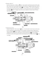
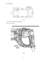
(2) Rotation only (Fig. 6)
Adjust the change lever to "rotation only" ( mark). The lock plate is moved forward by the pin of the change
lever, and the clutch is moved forward at the back end of the lock plate. Engagement between the clutch and
the claws of the reciprocating bearing is released ( A portion in the figure). Thus no rotation is transmitted to
the reciprocating bearing and hammering is stopped. On the other hand, the pinion sleeve engages with the
second pinion ( B portion in the figure), and so the rotation is transmitted to the pinion sleeve for "rotation
only" function.
Pinion sleeve
Released portion A
(Stop of hammering)
Lock plate
(Back end)
Engaged portion B
(Transmission of rotation)
Fig. 6
Claw of clutch
Pin of change lever
Claws of reciprocating bearing
Reciprocating bearing
Lock plate
(Front end)
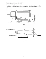
(3) Hammering only (Fig. 7)
Adjust the change lever to "hammering only" ( mark). The second pinion is moved to the motor side by the
pin of the change lever. Engagement between the pinion sleeve and the second pinion is released and no
rotation is transmitted ( B portion in the figure). The lock plate is moved to the motor side by spring (B) and
engaged with the locking claw of the second pinion to lock the cylinder rotation ( C portion in the figure).
On the other hand, the clutch engages with the reciprocating bearing for "hammering only" function ( A portion
in the figure).
Engaged portion C
(Lock of tool)
Released portion B
(Stop of rotation)
Lock plate
Second gear
Cylinder
Spring (B)
Pinion sleeve
Pin of change lever
Second pinion
Clutch
Locking claw of second pinion
Reciprocating bearing
Engaged portion A
(Transmission of hammering)
Second pinion
Clutch