


Deskstar 7K400 Hard Disk Drive Specification
117
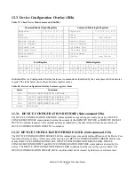
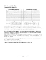
12.3.3 DEVICE CONFIGURATION IDENTIFY (Subcommand C2h)
The DEVICE CONFIGURATION IDENTIFY command returns a 512 byte data structure via PIO data-in transfer.
The content of this data structure indicates the selectable commands, modes, and feature sets that the device is
capable of supporting. If a DEVICE CONFIGURATION SET command has been issued reducing the capabilities,
the response to an IDENTIFY DEVICE or IDENTIFY PACKET DEVICE command will reflect the reduced set of
capabilities, while the DEVICE CONFIGURATION IDENTIFY command will reflect the entire set of selectable
capabilities.
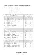
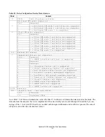
The format of the Device Configuration Overlay data structure is shown in Table 81: “Device Configuration Over-
lay Data structure” on page 118.
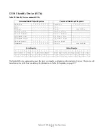
12.3.4 DEVICE CONFIGURATION SET (Subcommand C3h)
The DEVICE CONFIGURATION SET command allows a device manufacturer or a personal computer system
manufacturer to reduce the set of optional commands, modes, or feature sets supported by a device as indicated by
a DEVICE CONFIGURATION IDENTIFY command. The DEVICE CONFIGURATION SET command transfers
an overlay that modifies some of the bits set in words 63, 82, 83, 84, and 88 of the IDENTIFY DEVICE command
response. When the bits in these words are cleared, the device no longer support the indicated command, mode, or
feature set. If a bit is set in the overlay transmitted by the device that is not set in the overlay received from a
DEVICE CONFIGURATION IDENTIFY command, no action is taken for that bit.
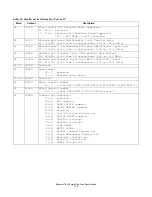
The format of the overlay transmitted by the device is described in the table in Table 81: “Device Configuration
Overlay Data structure” on page 118. The restrictions on changing these bits is described in the text following that
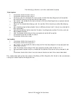
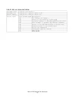
table. If any of the bit modification restrictions described are violated or any setting is changed with DEVICE
CONFIGURATION SET command, the device shall return command aborted. At that case, error reason code is
returned to sector count register, invalid word location is returned to cylinder high register, and invalid bit location
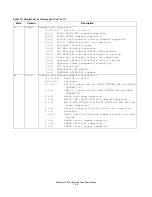
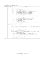
is returned to cylinder low register. The Definition of error information is shown in Table 82: “DCO error informa-
tion definition” on page 119.
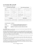
ERROR INFORMATION EXAMPLE 1:
If a user attempts to change maximum LBA address (DC SET or DC RESTORE) after establishing a protected area
with SET MAX address, the device will abort that command and returns error reason code as below.
ERROR INFORMATION EXAMPLE 2:
If the user attempts to disable that feature when the device is enabled and the Security feature is set, the device will
abort that command and returns an error reason code as below.
Cylinder high
: 03h = word 3 is invalid
Cylinder low
: 00h this register is not assigned in this case
Sector Number
: 00h this register is not assigned in this case
Sector count
: 06h = Protected area is now established
Cylinder high
: 07h = word 7 is invalid
Cylinder low
: 00h = bit 8-15 are valid
Sector Number
: 00h = bit 3 is invalid
Sector count
: 04h = Security feature set is now enabled
Summary of Contents for Deskstar 7K400
Page 2: ......
Page 18: ...Deskstar 7K400 Hard Disk Drive Specification 4 ...
Page 20: ...Deskstar 7K400 Hard Disk Drive Specification 6 ...
Page 21: ...Deskstar 7K400 Hard Disk Drive specification 7 Part 1 Functional specification ...
Page 22: ...Deskstar 7K400 Hard Disk Drive Specification 8 ...
Page 24: ...Deskstar 7K400 Hard Disk Drive Specification 10 ...
Page 34: ...Deskstar 7K400 Hard Disk Drive Specification 20 ...
Page 36: ...Deskstar 7K400 Hard Disk Drive Specification 22 ...
Page 58: ...Deskstar 7K400 Hard Disk Drive Specification 44 ...
Page 78: ...Deskstar 7K400 Hard Disk Drive Specification 64 ...
Page 80: ...Deskstar 7K400 Hard Disk Drive Specification 66 ...
Page 88: ...Deskstar 7K400 Hard Disk Drive Specification 74 ...
Page 116: ...Deskstar 7K400 Hard Disk Drive Specification 102 ...
Page 270: ...Deskstar 7K400 Hard Disk Drive Specification Write cache 94 Write DMA 226 ...


