background image

SPECIFICATIONS AND PARTS ARE SUBJECT TO CHANGE FOR IMPROVEMENT.


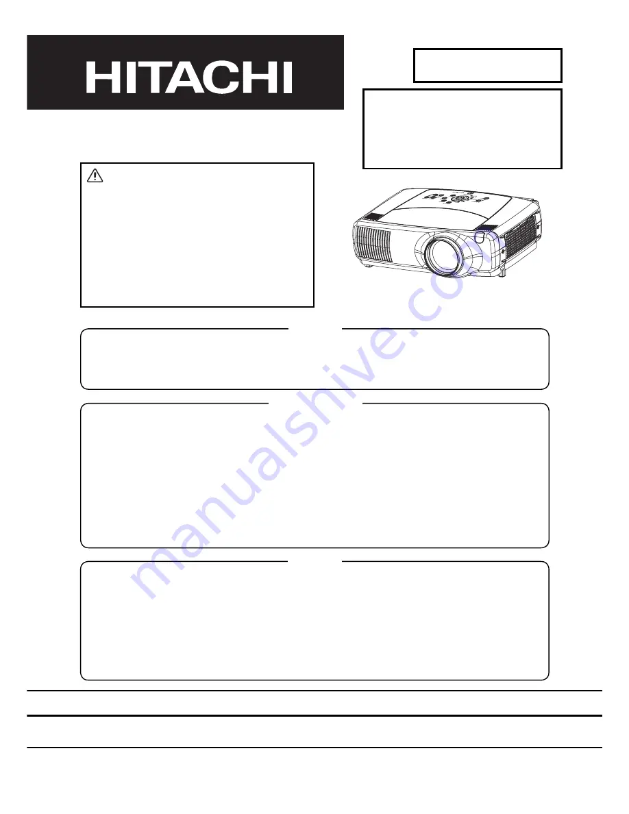
Multimedia LCD Projector

March  2004

   Digital Media Division

SM0542

SERVICE MANUAL

Be sure to read this manual before servicing.  To assure safety from 

fi

 re, electric shock, injury, harmful radi-

ation and materials, various measures are provided in this Hitachi Multimedia LCD Projector.  Be sure to 
read cautionary items described in the manual to maintain safety before servicing.

Caution


1. When replac

ing

 the lamp, avoid burns to your 

fi

 ngers

 as


t

he lamp becomes 

very

 hot.

2. Never touch the lamp bulb with a 

fi

 nger or anything else.  Never drop it or give it a shock.  They may 

cause bursting of the bulb.

3. This projector is provided with a high voltage circuit for the lamp.  Do not touch the electric parts of 

power unit (main), when turn

ing

 on the projector.

4. Do not touch the exhaust fan, during operation.
5. The LCD module assembly is likely to be damaged.  If replacing the LCD LENS/PRISM assembly, do 

not hold the FPC of the LCD module assembly.

6. Use the cables which are included with the projector or 

as 

speci 

fi

 ed.

Service Warning


1.  Features --------------------------------------------------- 2
2.  Speci

fi

 cations--------------------------------------------- 2

3.  Names of each part ------------------------------------- 3
4.  Adjustment ------------------------------------------------ 5
5.  Troubleshooting---------------------------------------- 12
6.  Service points ------------------------------------------ 18
7.  Wiring diagram ----------------------------------------- 29

8.  Disassembly diagram--------------------------------- 36
9.  Replacement parts list-------------------------------- 39
10.RS-232C communication ---------------------------- 4

0

11.Block diagram------------------------------------------- 5

0

12.Connector connection diagram -------------------- 5

1

13.Basic circuit diagram---------------------------------- 5

2

Contents 


Warning

The technical information and parts shown in this 
manual are not to be used for: the development, 
design, production, storage or use of nuclear, chemical,   
biological or missile weapons or other weapons of 
mass destruction; or military purposes; or purposes that 
endanger global safety and peace. Moreover, do not 
sell, give, or export these items, or grant permission for 
use to parties with such objectives. Forward all inquiries 
to Hitachi Ltd.

CP-X1200W

(P5XLA)

CP-X1250W

(P5XMLA)

CP-X1200WA

(P5XMLB)

PJ1165

(P5XMB)

Summary of Contents for CP-X1200W

Page 1: ... operation 5 The LCD module assembly is likely to be damaged If replacing the LCD LENS PRISM assembly do not hold the FPC of the LCD module assembly 6 Use the cables which are included with the projector or as specified Service Warning 1 Features 2 2 Specifications 2 3 Names of each part 3 4 Adjustment 5 5 Troubleshooting 12 6 Service points 18 7 Wiring diagram 29 8 Disassembly diagram 36 9 Replac...

Page 2: ... 525p 480p 625i 575i 720p 1080i Y 1 0Vp p 75Ω terminator RCA jack 3 BNC 3 CB CR 0 7Vp p 75Ω terminator PB PR 0 7Vp p 75Ω terminator AUDIO IN L 200mVrms 57kΩ max 3 0Vp p RCA jack 2 R Signal output RGB OUT Video Analog 0 7Vp p 75Ω output impedance positive H V sync TTL level positive negative Composite sync TTL level D sub 15 pin shrink jack AUDIO OUT 0 200mVrms output impedance 1kΩ Stereo mini jack...

Page 3: ... L L S S L L S L 9S S ȍ WHUPLQDWRU 5 MDFN 1 5 9S S ȍ WHUPLQDWRU 5 MDFN 1 3 35 9S S ȍ WHUPLQDWRU 5 MDFN 1 8 2 1 P9UPV Nȍ PD 9S S 5 MDFN î 5 6LJQDO RXWSXW 5 287 9LGHR QDORJ 9S S ȍ RXWSXW LPSHGDQFH SRVLWLYH 9 V QF 77 OHYHO SRVLWLYH QHJDWLYH RPSRVLWH V QF 77 OHYHO VXE SLQ VKULQN MDFN 8 2 287 a P9UPV RXWSXW LPSHGDQFH Nȍ 6WHUHR PLQL MDFN 287 9 3RZHU VXSSO IRU WKH LUHOHVV XQLW 6SHDNHU RXWSXW VWHUHR 3RZHU...

Page 4: ... OUT port M AUDIO OUT port 7 REMOTE CONTROL port 8 DC OUT port 9 AC Inlet 10 Power switch Projector Front Right Projector Rear Left 1 2 3 5 6 4 9 10 ENTER INPUT M1 D RGB BNC S VIDEO STANDBY ON TEMP VIDEO COMPONENT LAMP KEYSTONE SEARCH RESET MENU FOCUS LENS SHIFT ZOOM Control Panel STANDBY ON button and STANDBY ON indicator TEMP indicator LAMP indicator LENS SHIFT buttons INPUT dial SEARCH button M...

Page 5: ...tton is pressed About the Laser pointer WARNING The laser pointer of the remote control is used in place of a finger or rod Never look directly into the laser beam outlet or point the laser beam at other people The laser beam can cause vision problems CAUTION Use of controls or adjustments or performance of procedures other than those specified herein may result in hazardous radiation exposure STA...

Page 6: ...ide to Max And project an image with more than 1m 40 inches in diagonal size 3 Shift the Lens to the highest position with the LENS SHIFT button 4 Normalizing the video adjustment Press the MENU button of the Remote control transmitter to display the MAIN menu After pressing the key use the or key to select RESET Reset menu will appear by the key then choose EXECUTE Next open the PICTURE1 menu Cho...

Page 7: ...use DAC P V COM G in the FACTORY MENU to adjust the G color flicker 4 In the same way use DAC P V COM B in the FACTORY MENU to adjust the B color flicker 4 2 Ghost adjustment Signals for internal adjustment 30 30 112 255 0 255 Adjustment procedure 1 Use DAC P GHOST R in the FACTORY MENU to adjust so that R color ghost is at a minimum Set the adjustment value to default and then raise the value Whe...

Page 8: ...e is best 8 Adjust GAMMA SB CNT R and B in the FACTORY MENU so that middle brightness white balance is best 9 Repeat steps 7 to 8 above and adjust so that brightness white balance of 29 steps is best 4 4 NRSH adjustment vertical stripe adjustment Signals for internal adjustment 192 255 168 255 144 255 120 255 96 255 72 255 48 255 24 255 Adjustment procedure 1 Make this adjustment after completing ...

Page 9: ...white balance for each of the points starting in order from the low numbers 5 Adjustment point No 1 should not be adjusted because it controls the brightness of the entire screen 6 To temporarily turn correction off place the cursor on C UNIF in the Adjust Tone menu and press the key The ON OFF menu appears Place the cursor on ON with the key and press the key To turn it on again place the cursor ...

Page 10: ...oint No 2 and adjust No 2 R and B so that the coordinates are as follows x x1 0 005 y y1 0 010 9 Similarly measure adjustment points No 3 to No 17 and adjust their color coordinates starting in order from the small number points This completes adjustments required for MIN Note Since excessive correction may lead to a correction data overview during internal calculations use the following values fo...

Page 11: ...eased Overall a cyan cast makes it easy to see color shading 7 Next view measurement points No 4 No 5 No 12 No 13 and make similar adjustments 8 Then adjust measurement points No 6 No 7 No 8 No 9 No 14 No 15 No 16 and No 17 This completes the MIN tone adjustments 9 Make similar another three tones as described in steps 1 to 8 above 8 3 16 17 9 11 6 14 2 12 15 13 10 7 4 1 5 8 3 16 17 9 11 14 12 15 ...

Page 12: ...IFY OFF button for 3 seconds or more 3 Press the button Next press the button to select EXECUTE The adjustment program runs automatically 4 After the massage of END is displayed check the Offset value displayed according to the following spec Spec 10 Offset 65 5 If out of spec confirm the below conditions Then retry the same adjustment Description a Installing the air filter correctly b No obstruc...

Page 13: ...E807 E808 E804 E811 E800 E805 E809 E303 E302 E304 TSW IS01 PWB assembly SENSOR TH950 PWB assembly DRIVE PWB assembly SIGNAL PWB assembly KEYPAD TXP29 TXP26 TXP23 TXP20 TXP19 SPEAKERS DK53 DK52 Q801 Collector TP FS2 TP FS CHV35 1 8 4 5 81 1 31 51 CHV36 CHV29 CHV33 CHV26 CHV34 CHV27 CHV28 IV02 IV01 TEMP SENSOR 5 Troubleshooting Check points ...

Page 14: ...on Power unit circuit NO YES Disconnect TSW from Power unit circuit And check TSW short or open PWB assembly Drive Short TSW Open Lights What is the state of LAMP indicator DK52 Not light Blinks 1 1 2 4 6 12 Is the LAMP connection OK Set the LAMP again Is the voltage at pin and of E807 same NO YES PWB assembly Limit SW PWB assembly Drive Is the LAMP COVER set OK Set the LAMP COVER NG NG Lamp Power...

Page 15: ...AMP E808 Is the voltage at collector of Q801 on the PWB assembly Drive fixed to L during warming up L 0V DC FAN Measure the voltage at each pin Set AC to ON and enter standby status The voltage is H 3 3V H 3 3V H 3 3V Measure sure voltage at TP FS and or TP FS2 on the PWB assembly Drive Turn on the power supply and check the voltage Check the fan connector connection Connector connection Normal OK...

Page 16: ... Drive 16 5V 15V 4V 6V E800 E800 E800 E800 1 4 6 12 Power unit circuit NO YES Are voltage input at each pin on the PWB assembly Drive Are signal input at these pins of EV01 on the PWB assembly Drive NO YES NO YES PWB assembly Signal IC IV01 TC90A92AFG IC IV02 MM1113XF PWB assembly Drive Check at operating mode CHV29 VIDEO Composite CHV28 S VIDEO Y CHV27 S VIDEO C CHV34 Component Y CHV35 Component ...

Page 17: ...d measure their resistance Are voltage input at each pin on the PWB assembly Drive CHV26 Audio L CHV33 Audio R 16 5V 15 0V 4 0V 6 0V 6 0V E800 E800 E800 E800 E811 1 1 4 6 12 The check after parts change 1 PC power supply OFF 2 Connection of cable 3 Projector starting 4 PC starting When not operating PC set up change of cable Can not control to RS 232C PWB assembly Drive NO YES NO YES Use cross cab...

Page 18: ...Is the DHCP in the Settings Network menu activated with the checked mark NO NO Is the computer connected with the projector directly Is either IP address or Subnet Mask in the Setting Network Network Info menu set to 0 0 0 0 If Subnet Mask is 255 255 255 0 are xxx yyy zzz portion of IP address setting of computer and projector same PWB assembly Drive YES YES Is there DHCP server on the network whi...

Page 19: ...ghly after the lead free solder has been completely melted do not apply the soldering iron without solder Servicing soldering iron A soldering iron with a temperature setting capability temperature control function is recommended The melting point of lead free solder is higher than leaded solder Use a soldering iron that maintains a high stable temperature large heat capacity and that allows tempe...

Page 20: ...pets Use only the battery specified two AA batteries Do not mix new battery with used one Make sure the plus and minus terminals are correctly aligned when loading the battery as indicated in the remote control Dispose of batteries in accord with environmental laws 1 Remove the battery cover Slide back and remove the battery cover in the direction of the arrow 2 Insert the batteries Align and inse...

Page 21: ...ctor and unplug the power cord Allow the lamp bulb to cool for at least 45 minutes 2 After making sure that the projector has cooled adequately remove the filter cover and air filter 3 Apply a vacuum cleaner to the top of the filter cover and the air filter to clean If the soiling will not come off the air filter or it becomes damaged it needs to be replaced 4 Insert the cleaned air filter or a ne...

Page 22: ... get it in your eyes or mouth Before replacing the lamp make sure the power switch is off and the power cable is not plugged in then wait at least 45 minutes for the lamp to cool sufficiently Handling the lamp while hot can cause burns as well as damaging the lamp Do not open the lamp cover while the projector is suspended from above This is dangerous since if the lamp s bulb has broken the shards...

Page 23: ...sult in incorrect message functions CO LAMP PC INTER INPUT M1 D RGB BNG S VIDEO ST ANDBY ON TEMP VIDEO COMPONENT LAMP KEYSTONE SEARCH RESET MENU FOCUS LENS SHIFT ZOOM Lamp cover Lamp cover knob Tabs INTER INPUT M1 D RGB BNG S VIDEO ST ANDBY ON TEMP VIDEO COMPONENT LAMP KEYSTONE SEARCH RESET MENU FOCUS LENS SHIFT ZOOM CO LAMP PC CO LAMP PC INTER INPUT M1 D RGB BNG S VIDEO ST ANDBY ON TEMP VIDEO COM...

Page 24: ...at the rear of the lens 2 Do not touch the terminals 3 Do not pull the wires 5 Mount the replacement lens 1 Align the red mark on the lens with the red mark on the lens holder and insert the lens into the holder 2 Turn the lens clockwise until a click is heard Attach the lens so that the red mark on the lens and the green mark on the holder are aligned 3 Confirm that the lens is securely locked 4 ...

Page 25: ...e listed below including benzene and paint thinner Do not use aerosols or sprays Do not polish or wipe with hard objects Caring for the inside of the projector In order to ensure the safe use of your projector please have it cleaned and inspected by your local dealer about once every 2 years Caring for the lens 1 Turn off the projector and unplug the power cord 2 Lightly wipe the lens with a comme...

Page 26: ...eriod of blanking on signal processing To avoid such phenomena AUTO function should be used with the full size picture that has bright tone on its peripheral Note 1 The phenomenon at the failure of AUTO adjustment depends on resolution of input source scene of picture etc 2 There is no failure above in AUTO with video source through VIDEO S VIDEO or COMPONENT input The reason is why recognition of...

Page 27: ...IR FILTER RESET THE FILTER TIMER It is time to clean the air filter Please immediately turn the power OFF and clean or change the air filter by referring to the Air Filter section of this manual After you have cleaned or changed the air filter please be sure to reset the filter timer If the same message is displayed after the treatment please clean the metal pieces of filter cover and the dust det...

Page 28: ...DWXUH LV ULVLQJ 3OHDVH WXUQ WKH SRZHU 2 DQG DOORZ WKH XQLW WR FRRO GRZQ DW OHDVW PLQXWHV IWHU WKH SURMHFWRU KDV VXI FLHQWO FRROHG GRZQ SOHDVH PDNH FRQ UPDWLRQ RI WKH IROORZLQJ LWHPV DQG WKHQ WXUQ WKH SRZHU 21 DJDLQ V WKHUH EORFNDJH RI WKH DLU SDVVDJH DSHUWXUH V WKH DLU OWHU GLUW RHV WKH SHULSKHUDO WHPSHUDWXUH H FHHG DULQJ RI WKH 0HWDO 3LHFHV RI ILOWHU FRYHU DQG WKH GXVW GHWHFWLQJ ZLQGRZV 7KH PHWDO...

Page 29: ...ge aperture Is the air filter dirty Does the peripheral temperature exceed 35 C If the same indication is displayed after the treatment please change the lamp by referring to the section Lamp Lighting or blinking in red Blinking in red Turned off Either there is no lamp and or lamp cover or either of these has not been properly fixed Please turn the power off and allow the unit to cool down at lea...

Page 30: ...N ON on the OSD using button TURN OFF Select the TURN OFF on the OSD using button 3 The OSD will be ended by no operation for 10 seconds or change of input signal To end immediately use one of buttons except buttons 6 12 Set operating time display method accumulated lamp time display method 1 Select OPTION from the MENU display then select LAMP TIME 2 Press the RESET button once then press KEYSTON...

Page 31: ...ch when reducing slack so as not to compromise the connectors CNPW1 CNPW2 TSW CN102 CN103 CN104 Becarefulnottoliftthe connectorsinthethreespots asdepictedintheillustration atleft Theconnectionshavebecome compromised Exampleofcompromised connections 2 Wiring of the ballast board for assembling the ballast board sub assembly Lamp leads CNBAR Pass the CNBAR cable through the notch in the ballast hold...

Page 32: ...oard Ballast board Make sure that the CNBAR does not droop on top of the ballast board Maintain a safe distance Prevents the CNBAR from coming into contact with the fan blades Make sure that the lines do not protrude from the notch of the ballast cover Prevents tangling Pull the CNPWR cables to the left in the direction of the arrow in the diagram below when placing the ballast board on top of the...

Page 33: ...n the diagram at right They need to be configured so that they do not catch on the lens or the motor s gears Connect the cable end that is closest to its binding Tapes to the connector beside the lens Do not stress the flexible cable for the lens when wiring the CNLS cable TAP2 FRONT VIEW Lens 680 Lamp fan Protruding part Cover the protruding portion of the clasp with tape As per the assembly diag...

Page 34: ...cables come out the side of the power block as per the diagram Wire the lamp leads by passing them underneath the lamp housing Secure the connectors for the lamp leads to the lamp housings When doing so pay attention to the polarity of the connectors If the lamp leads are too long push the surplus length up into the empty space beneath the connectors Wiring diagram 4 P5XLA P5XMLA P5XMLB Lamp lead ...

Page 35: ... the TSW leads through the notch in the ballast holder Before attaching the exhaust fan duct send the TSW leads from the side behind the duct install the TSW first then the fan duct Surplus leads cannot be left inside the duct so pass them through the side of the ballast holder Verify the type of TSW and install it so that stamped designation is visible YS11A120A Push the TSW lamp temperature swit...

Page 36: ...t the CNLS cable to the EW51 connector Drive board Connect the flexible cables for the red green and blue panels to their respective P501 601 and P701 connectors CNTH Connect the CNTH cables to the E302 connector 3054 Connect the 3054 fan leads to the E809 connector CNBAR Connect the CNBAR cable to the E805 connector CNPW1 CNPW2 Connect the CNPW1 cable to the E800 connector Connect the CNPW2 cable...

Page 37: ...urplus length of cables under the drive board so that they do not get caught when attaching the upper case Push any surplus length of cables under the drive board so that they do not get caught when attaching the upper case CNSW2 CNSW1 CNTH 3054 E303 E304 Connect the CNSW1 and CNSW2 cables to the E303 and E304 connectors of the drive board with the upper case in an upright position Upper case Keyp...

Page 38: ...36 CP X1200 P5XLA CP X1250 P5XMLA CP X1200WA P5XMLB 8 Disassembly diagram M Meter screw T Tapping screw ...

Page 39: ... a 3 3 0 LVDVVHPEO GLDJUDP 0 0HWHU VFUHZ 7 7DSSLQJ VFUHZ ...

Page 40: ...37 CP X1200 P5XLA CP X1250 P5XMLA CP X1200WA P5XMLB PJ1165 P5XMB M Meter screw T Tapping screw ...

Page 41: ...the Drive board disconnect the all cables from connectors on it 2 Lift up the Drive board straightly to disconnect two board to board connectors on the opposite side of it after taking off the screws of it Board to board connectors PWB assembly Drive When removing the optical unit move it it the direction of the arrow so that the protuberance of the optical unit fan does not become caught in the i...

Page 42: ...pe Type Power cord UK Type Power Cord US Type RGB cable Video Audio cable MI D cable or Instruction manual Cleaning tool for dust Cotton stick L70 ST ANDBY ON VIDEO LASER INDICA T OR ESC MENU POSITION RESET A UT O KEYST ONE 1 2 3 ID CHANGE SEARCH ON OFF FREEZE MUTE MA GNFY PinP VO L UME RGB BLANK PREVIOUS NEXT ASPECT MOUSE LASER LENS SHIFT FOCUS ZOOM Component video cable PJ1165 ...

Page 43: ...RD TD GND CTS RTS 1 2 3 4 5 6 7 8 9 CD RD TD DTR GND DSR RTS DTS RI Projector RS 232C cross cable Computer 6 7 8 9 5 4 3 2 1 9 8 7 6 1 2 3 4 5 6 7 8 9 5 4 3 2 1 9 8 7 6 1 2 3 4 5 Communications setting 19200bps 8N1 1 Protocol Consist of header 7 bytes command data 6 bytes 2 Header BE EF 03 06 00 CRC_low CRC_high CRC_low Lower byte of CRC flag for command data CRC_high Upper byte of CRC flag for co...

Page 44: ...rojector setting value Decrement command 1 The computer sends the decrement code Header Command data 05H 00H type 2 bytes 00H 00H to the projector 2 The projector decreases the setting value on the above setting code 3 The projector returns the response code 06H to the computer When the projector cannot understand the received command When the projector cannot understand the received command the e...

Page 45: ... BE EF 03 06 00 58 D3 06 00 00 70 00 00 Contrast Get BE EF 03 06 00 FD D3 02 00 04 20 00 00 Increment BE EF 03 06 00 9B D3 04 00 04 20 00 00 Decrement BE EF 03 06 00 4A D2 05 00 04 20 00 00 Contrast Reset Execute BE EF 03 06 00 A4 D2 06 00 01 70 00 00 Aspect Set 4 3 BE EF 03 06 00 9E D0 01 00 08 20 00 00 16 9 BE EF 03 06 00 0E D1 01 00 08 20 01 00 SMALL BE EF 03 06 00 FE D1 01 00 08 20 02 00 NORMA...

Page 46: ...03 06 00 A7 F1 01 00 A1 30 02 00 CUSTOM BE EF 03 06 00 07 FD 01 00 A1 30 10 00 Get BE EF 03 06 00 F4 F0 02 00 A1 30 00 00 Custom Gamma Get BE EF 03 06 00 08 F1 02 00 A0 30 00 00 Increment BE EF 03 06 00 6E F1 04 00 A0 30 00 00 Decrement BE EF 03 06 00 BF F0 05 00 A0 30 00 00 Custom Color Temp Set USER BE EF 03 06 00 3B F8 01 00 B0 30 10 00 HIGH BE EF 03 06 00 0B F5 01 00 B0 30 03 00 MIDDLE BE EF 0...

Page 47: ...6 00 23 D2 04 00 06 20 00 00 Decrement BE EF 03 06 00 F2 D3 05 00 06 20 00 00 Color Balance B Reset Execute BE EF 03 06 00 D0 D3 06 00 06 70 00 00 Sharpness Get BE EF 03 06 00 F1 72 02 00 01 22 00 00 Increment BE EF 03 06 00 97 72 04 00 01 22 00 00 Decrement BE EF 03 06 00 46 73 05 00 01 22 00 00 Sharpness Reset Execute BE EF 03 06 00 C4 D0 06 00 09 70 00 00 Color Get BE EF 03 06 00 B5 72 02 00 02...

Page 48: ... 00 Increment BE EF 03 06 00 F7 70 04 00 09 22 00 00 Decrement BE EF 03 06 00 26 71 05 00 09 22 00 00 Over Scan Reset Execute BE EF 03 06 00 EC D9 06 00 27 70 00 00 Color Space Set AUTO BE EF 03 06 00 0E 72 01 00 04 22 00 00 RGB BE EF 03 06 00 9E 73 01 00 04 22 01 00 SMPTE240 BE EF 03 06 00 6E 73 01 00 04 22 02 00 REC709 BE EF 03 06 00 FE 72 01 00 04 22 03 00 REC601 BE EF 03 06 00 CE 70 01 00 04 2...

Page 49: ... 06 00 CB D3 01 00 00 30 03 00 White BE EF 03 06 00 6B D0 01 00 00 30 05 00 Black BE EF 03 06 00 9B D0 01 00 00 30 06 00 Get BE EF 03 06 00 08 D3 02 00 00 30 00 00 Blank on off Set TURN OFF BE EF 03 06 00 FB D8 01 00 20 30 00 00 TURN ON BE EF 03 06 00 6B D9 01 00 20 30 01 00 Get BE EF 03 06 00 C8 D8 02 00 20 30 00 00 Startup Set My Screen BE EF 03 06 00 CB CB 01 00 04 30 20 00 Original BE EF 03 06...

Page 50: ...3 06 00 CB D3 05 00 07 30 00 00 Freeze Set Normal BE EF 03 06 00 83 D2 01 00 02 30 00 00 Freeze BE EF 03 06 00 13 D3 01 00 02 30 01 00 Get BE EF 03 06 00 B0 D2 02 00 02 30 00 00 Power Set TURN OFF BE EF 03 06 00 2A D3 01 00 00 60 00 00 TURN ON BE EF 03 06 00 BA D2 01 00 00 60 01 00 Get BE EF 03 06 00 19 D3 02 00 00 60 00 00 Example Return 00 00 01 00 02 00 Off On Cool down Input Source Set M1 D BE...

Page 51: ...00 00 PinP Input Set Video BE EF 03 06 00 D6 22 01 00 02 23 01 00 S Video BE EF 03 06 00 26 22 01 00 02 23 02 00 Get BE EF 03 06 00 75 23 02 00 02 23 00 00 Myscreen size Set Full BE EF 03 06 00 43 D6 01 00 12 30 00 00 X1 BE EF 03 06 00 D3 D7 01 00 12 30 01 00 Get BE EF 03 06 00 70 D6 02 00 12 30 00 00 Myscreen Lock Set Off BE EF 03 06 00 3B EF 01 00 C0 30 00 00 On BE EF 03 06 00 AB EE 01 00 C0 30 ...

Page 52: ...1C 20 00 00 TURN ON BE EF 03 06 00 FE D4 01 00 1C 20 01 00 Get BE EF 03 06 00 5D D5 02 00 1C 20 00 00 Lens Lock Set TURN OFF BE EF 03 06 00 FF 97 01 00 10 24 00 00 TURN ON BE EF 03 06 00 6F 96 01 00 10 24 01 00 Get BE EF 03 06 00 CC 97 02 00 10 24 00 00 Remote ID Set All BE EF 03 06 00 9F 30 01 00 08 26 00 00 1 BE EF 03 06 00 0F 31 01 00 08 26 01 00 2 BE EF 03 06 00 FF 31 01 00 08 26 02 00 3 BE EF...

Page 53: ...ideo RGB Audio Out SP M1D REMC PWB SIGNAL PWB SIGNAL SELECTOR R sirocco G sirocco B sirocco Lamp sirocco Power Exhaust VOLUME CONTROL AUDIO_AMP BNC RGB RS 232C DC POWER REGULATOR 0 99 XGA LCD PANEL SW PWB SW MOTOR DAC S P SW SENS PWB X tal Spread S SG 9001 TMDS RECEIVER with HDCP SiI169 DDC Wired RC Image_PROCESSOR MAIN CPU PW463A 10V S H L S L3E06100 MCLK IR RECEIVER IR RECEIVER IR RECEIVER KEYPA...

Page 54: ...0 MON 2 LOUT 23 GND 8 ESPR 24 GND 9 1 ROUT BNC IN ES02 25 RGB H INV 10 2 ROUT 26 RGB V INV 11 SPEAKER 27 RGB1 2 12 E807 CNLC E941 28 5VST 13 1 OUT 1 PWB 29 5VST 14 2 COVER 2 assembly RGB OUT ES03 30 GND 15 SWITCH 1 GND 16 2 5VST 17 E804 3 5VST 18 1 FAN4S DC FAN 4 RGB1 2 19 2 EXHAUST EXHAUST 5 RGB V INV 20 3 GND 6 RGB H INV 21 7 GND 22 8 GND 23 E809 9 RGB B 24 1 FAN6S DC FAN 10 GND 25 2 INTAKE INTA...

Page 55: ...IMIT SWITCH POWER UNIT BALLAST POWER UNIT CIRCUIT PWB DRIVE 1 PWB DRIVE 2 PWB DRIVE 3 PWB DRIVE 4 PWB DRIVE 5 PWB DRIVE 6 PWB DRIVE 7 PWB DRIVE 8 PWB DRIVE 9 PWB DRIVE 10 PWB DRIVE 11 PWB DRIVE 12 PWB DRIVE 13 PWB DRIVE 14 PWB DRIVE 15 PWB DRIVE 16 PWB SIGNAL 1 PWB SIGNAL 2 PWB KEYPAD PWB DUST SENSOR Basic circuit diagram list ...

Page 56: ...53 CP X1200 P5XLA CP X1250 P5XMLA CP X1200WA P5XMLB PJ1165 P5XMB Parts with hatching are not mounted ...

Page 57: ...A B C D E F G 5 4 3 2 1 6 6 5 4 3 2 1 POWER UNIT BALLAST P5XLA P5XMLA For handling of the circuit diagram refer to the warning on the cover Warning ...

Page 58: ...A B C D E F G 5 4 3 2 1 6 6 5 4 3 2 1 POWER UNIT CIRCUIT P5XLA P5XMLA For handling of the circuit diagram refer to the warning on the cover Warning ...

Page 59: ...A B C D E F G 5 4 3 2 1 6 6 5 4 3 2 1 POWER UNIT BALLAST P5XMLB For handling of the circuit diagram refer to the warning on the cover Warning ...

Page 60: ...A B C D E F G 5 4 3 2 1 6 6 5 4 3 2 1 POWER UNIT CIRCUIT P5XMLB For handling of the circuit diagram refer to the warning on the cover Warning ...

Page 61: ......

Page 62: ......

Page 63: ......

Page 64: ......

Page 65: ......

Page 66: ......

Page 67: ......

Page 68: ......

Page 69: ......

Page 70: ......

Page 71: ......

Page 72: ......

Page 73: ......

Page 74: ......

Page 75: ......

Page 76: ......

Page 77: ......

Page 78: ......

Page 79: ......

Page 80: ......

Page 81: ......

Page 82: ......

Page 83: ......

Page 84: ......

Page 85: ......

Page 86: ......

Page 87: ......

Page 88: ......

Page 89: ......

Page 90: ......

Page 91: ......

Page 92: ......

Page 93: ......

Page 94: ......

Page 95: ......

Page 96: ......

Page 97: ...47 Milano Italia ITALY Tel 39 02 487861 Tel 39 02 38073415 Servizio Clienti Fax 39 02 48786381 2 Email customerservice italy hitachi eu com HITACHI Europe AB Box 77 S 164 94 Kista SWEDEN Tel 46 0 8 562 711 00 Fax 46 0 8 562 711 13 Email csgswe hitachi eu com HITACHI EUROPE S A S Lyon Office B P 45 69671 BRON CEDEX FRANCE Tel 04 72 14 29 70 Fax 04 72 14 29 99 Email france consommateur hitachi eu co...

Reviews: