background image


17

never use the plug with the cover omitted.  If a replacement fuse cover is 

required, ensure it is of the same colour as that visible on the pin face of the 

plug.  Fuse covers are available from your dealer. 

DO NOT cut off the mains plug from this equipment.  If the plug fitted is not 

suitable for the power outlets in your home or the cable is too short to reach a 

power outlet, then obtain an appropriate safety approved extension lead or 

consult your dealer. 

Should it be necessary to change the mains plugs, this must be carried out by a 

competent person, preferably a qualified electrician. 

If there is no alternative to cutting off the mains plug, ensure that you dispose of 

it immediately, having first removed the fuse, to avoid a possible shock hazard 

by inadvertent connection to the mains supply. 

WARNING: THIS EQUIPMENT MUST BE EARTHED  

IMPORTANT 

The wires in the mains lead are coloured in accordance with the 

following code: 

Green and Yellow = Earth, Blue = Neutral, Brown = Live. 

As these colours may not correspond with the coloured markings identifying 

the terminals in your plug, proceed as follows:   


Summary of Contents for CML170SXW

Page 1: ...ed on the rear of the monitor This monitor is ENERGY STAR compliant when used with a computer equipped with VESA DPMS The ENERGY STAR emblem does not represent EPA endorsement of any product or service As an ENERGY STAR Partner Hitachi Ltd has determined that this product meets the ENERGY STAR guidelines for energy efficiency USER MANUAL MANUEL D UTILISATION BEDIENUNGSANLEITUNG MANUAL DE USUARIO M...

Page 2: ...ducts and during their manufacture Since it is not so far possible to satisfactorily recycle the majority of electronics equipment most of these potentially damaging substances sooner or later enter nature There are also other characteristics of a computer such as energy consumption levels that are important from the viewpoints of both the work internal and natural external environments Since all ...

Page 3: ...erating layers of certain computer displays Cadmium damages the nervous system and is toxic in high doses The relevant TCO 99 requirement states thatbatteries the colour generating layers of display screens and the electrical or electronics components must not contain any cadmium Mercury Mercury is sometimes found in batteries relays and switches It damages the nervous system and is toxic in high ...

Page 4: ...e proof of purchase date with the monitor For additional information please write to Hitachi America Ltd 2000 Sierra Point Parkway MS 710 Brisbane CA 94005 1835 NEVER open the monitor cabinet If the monitor is not operating properly contact the HAL service center Call 1 800 536 6721 Do not open the monitor housing under any circumstances By opening the monitor housing you will expose yourself to h...

Page 5: ... failure caused by or resulting from the operation of the unit by incorrect voltages 10 The use of components that do not meet Hitachi specifications 11 Products sold in Canada by another organization which is not authorized by HITACHI CANADA LTD 12 Picture tube damages resulting from extended exposure of the video characters IMPORTANT This warranty is in lieu of all other warranties guarantees or...

Page 6: ...s that may appear in this manual The reproduction transmission or use of this documents or contents is not permitted without express written authority TRADEMARK ACKNOWLEDGEMENT VGA is a registered trademark of International Business Machines Corporation VESA is a trademark of a nonprofit organisation Video Electronics Standard Association ENERGYSTAR is a trademark of Environmental Protection Agenc...

Page 7: ...PLAY TO YOUR COMPUTER 22 CONNECTING THE ACPOWER 23 CONNECTING THE AUDIO CABLE 24 SETTING UP THE LCD MONITOR 24 POWER MANAGEMENT SYSTEM 24 CHAPTER 2 DISPLAY CONTROLS 25 USER CONTROLS 25 ADJUSTING THE MONITOR S DISPLAY 27 FUNCTION DESCRIPTIONS 28 CHAPTER 3 TECHNICAL INFORMATION 35 SPECIFICATIONS 35 STANDARD TIMING TABLE 38 TROUBLESHOOTING 40 ...

Page 8: ... within the graphic symbols Warning This symbolis used to indicate a hazard that may result in death or grave injury Caution hissymbol is used to indicate a hazard that may result in minor injury or significant damage to the product Notice example 1 Shock Caution This ê symbol indicates that caution should be taken and within the triangle ê is a picture depicting Shock caution Notice Example 2 Dis...

Page 9: ...d unplug the power cord Continued use in this condition may lead to electrical shock or fire The area around the cord should be clear to allow the cord to be easily unplugged Repair Modification Disassembly Do not attempt to repair modify or disassemble the product This may result in fire or electrical shock Air vents The air vents are to prevent the internal temperature from rising To not place i...

Page 10: ...ontaining water pins and paper clips or other metal items on the device If anything should fall in using the product in this condition may result in electrical shock Handling of the power cord Use the power cord supplied with the product and be careful of the following during use If handled improperly the cord may be damaged resulting in electrical shock or fire Never place objects on it DO not pu...

Page 11: ...re that electric plug is inserted in fully Check to see if there is no dust accumulated on the plug before plugging in Do not use a socket that is loose or wobbles Impact from Dropping To not drop bang or subject to physical shock Using after such incidents may result in electrical shock or fire Power Usage The usable voltage is 100 120V 200 240VAC DO notuse any other voltage This may result in el...

Page 12: ...ce at the location for a few hours before using Aluminum Electrolysis Condenser The electrolyte condenser used in the AC adapter has a limited life If used past the life span approximately 5 years replace the AC adapter Leakage or drying up of the electrolyte liquid may result in fire electrical shock This may also cause the device itself to malfunction Damage to the Display Unit Liquid may leak o...

Page 13: ...ly do not place objects that generate heat near the cables The cable casing may break and cause damage to the devices that are connected Stand When adjusting the angle hold the top left and right edges with both hands and move slowly Using only one hand may cause it to fall DO not place your hand near the stand when adjusting the LCD forward or back Your fingers may get caught and cause injury Eye...

Page 14: ...fere with each other s performances Especially for devices such as radios and televisions noise may enter their sound reception If this should happen try thefollowing Place in a location as far away from radios and televisions as possible Change the facing of the antenna on the radio or television Use a different electrical socket Storing the Plastic Bag Keep the plastic bag used to wrap the displ...

Page 15: ...reception which can be determined by turning the equipment off and on the user is encouraged to try to correct the interference by one or more of the following measures Reorient or relocate the receiving antenna Increase the separation between the equipment and receiver Connect the equipment into an outlet on a circuit different from that to which the receiver is connected Consult the dealer or an...

Page 16: ...nce and 2 Thisdevicemustacceptanyinterferencereceived including interference that may causeundesired operation The above named party is responsible for ensuring that the equipment complies with the standards of 47CFR 15 101 to 15 109 Trade name Color Monitor Model Number CML170SXW CML170SXJ Signature of Party Responsible Printed name of Party Responsible Hideaki Kusaba Executed on Date at Place Se...

Page 17: ...our dealer Should it be necessary to change the mains plugs this must be carried out by a competent person preferably a qualified electrician If there is no alternative to cutting off the mains plug ensure that you dispose of it immediately having first removed the fuse to avoid a possible shock hazard by inadvertent connection to the mains supply WARNING THIS EQUIPMENT MUST BE EARTHED IMPORTANT T...

Page 18: ... marked with the letter E or by the earth symbol or coloured GREEN or GREEN and YELLOW The wire coloured BLUE must be connected to the terminal marked with the letter N or coloured BLUE or BLACK The wire coloured BROWN must be connected to the terminal marked with the letter L or coloured BROWN or RED ...

Page 19: ... ensure that the Monitor does not become too hot After you unpack the LCD Monitor make sure that the following items were included in the box l LCD Monitor l 1 5M Monitor to PC signal Cable l 1 5M Stereo Jack Audio Cable l 1 8M Power Cord l User s Manual l AC Adapter If you find that any of these items is missing or appears damaged contact your dealer immediately Viewing Angle Adjustment The LCD M...

Page 20: ...e the Monitor and an Monitor stand Cable Installation Please follow these instructions to install the cables 1 Remove the back panel from the rear of the monitor See Fig 1 2 2 Remove the rear support panel from the swivel base support column See Fig 1 2 3 Place the signal cable the DC power cable and the audio cable into correct grooves See Fig 1 3 ...

Page 21: ...21 4 1 Figure 1 2 Figure 1 3 ...

Page 22: ...e to the VGA port on the PC 8 Make sure both connections are secure Video Connector Video Port Figure 1 4 ATTENTION This device must be connected to an off the shelf video cable in order to comply with FCC regulations A ferrite loaded interface cable is included in the LCD Monitor package This device will not be in compliance with FCC regulations when a non ferrite core video cable is used ...

Page 23: ...onitor 11 Connect the power cord to an AC power source DC Power Jack Power Cord Figure 1 5 WARNING Please install a Surge Protector device between the AC Adapter and the electrical wall outlet for added protection against power surges to prevent the effects of sudden voltage variations from reaching the LCD Monitor Sudden power surges may damage your monitor ...

Page 24: ... the LCD Monitor 14 Make sure the AC Adapter is connected to the LCD Monitor 15 Turn on the LCD Monitor s power switch located on the bezel of the monitor Power Management System This LCD Monitor complies with the VESA DPMS version 1 0 Power Management guidelines The VESA DPMS provides four power saving modes through detecting a horizontal or vertical sync signal When the LCD Monitor is in power s...

Page 25: ...ase Volume Turn knob Clockwise Decrease Volume Turn knob Counter Clockwise 3 DC Power Switch Press the power switch to switch the monitor ON OFF 4 DC Power On Indicator LED displays Green color Power is ON LED displays Dark color Power is OFF LED displays Yellow color Monitor is in Power Saving Mode 5 Function Select Buttons Press either the left or right control button for the OSD On Screen Displ...

Page 26: ...s Press the left button to decrease the value or the right button to increase the value of the chosen OSD setting 7 External Headphone Jack The monitor speakers will be disabled when using an external headphons or external speakers ...

Page 27: ...mplete during which a Auto Adjusting message will be shown on your screen The monitor has four function control keys among the functions shown on the OSD menu designed to create an easy user viewingenvironment OSD Function Menu To access the OSD Main menu simply press one of the Function Select Control buttons and the menu dialog box will pop up on the screen as shown below Continue pressing the F...

Page 28: ...phase to obtain the best viewing settings This process will take 3 5 seconds to complete ATTENTION After Auto Adjustment the display might display wrong position or size if it has received a pattern which has no screen border Save Exit Saves the values of this setting and exits the OSD menu function ...

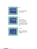
Page 29: ...ess 256 scales of brightness are available to choose from 0 to 255 Contrast 100 scales of contrast are available to choose from 0 to 99 Horizontal Position This function will adjust display s horizontal position ...

Page 30: ...s you select the images sharpness Five selections are available A smoother setting is more suitable for pictures while a sharper setting is more suitable for text Transparency This function set the transparency of the OSD menu The transparency is adjustable from 0 to 100 64 scales are available ...

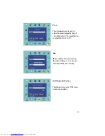
Page 31: ...frequency tracking feature that offers user better stability and clarity 127 scales from 63 to 63 are available on the mode that is currently running The adjustable range can be variable in different modes Color Temp Push the button to select a different color temperature Please see the diagram below for function and description ...

Page 32: ...magnification of video information The magnification is adjustable from 1 to 20 Pan If user enables the zoom function the enlarged image can be panned both horizontally and vertically OSD Horizontal Position This function moves the OSD menu windowhorizontally ...

Page 33: ... Text Because the H and V Freqentiesof both 640 x 400 70Hz and 720 x 400 70Hz are the same this function let s you manually select either 640 x 400 graphics mode or 720 x 400 text mode Recall The recall function will set all adjusted parameters to preset factory preset default values ...

Page 34: ...rdinate Color Temperature of 9300 K Sets the CIE coordinate color temperature to 9300 K 6500 CIE coordinated Color Temperature of 6500 K Sets the CIE coordinate color temperature to 6500 K 7500 CIE coordinated Color Temperature of 7500 K Sets the CIE coordinate color temperature to 7500 K User Three colors Red Green Blue can be adjusted from the OSD menu Sets the settings to a by user defined CIE ...

Page 35: ... matrix color TFT LCD 1280 x 1024 1280 x RGB x 1024 337 92 x 270 34 H x V 16 7M 200 cd m 2 typical 200 1 min 34 39 ms typical 690 Vrms typical 13 0 mA rms typical Vertical 80 80 Horizontal 80 80 Video Input Signal Input Impedance Polarity Amplitude Multi mode Supported Analog RGB 0 7Vp p 75 ohm 2 Positive 0 0 7 0 05 Vp Horizontal Frequency 24 80 KHz Vertical Frequency 56 85 Hz Control Power ON OFF...

Page 36: ...er Consumption AC Input LED Color ON 54W maximum 240 VAC Green Standby 5W maximum 240 VAC Yellow Suspend 5W maximum 240 VAC Yellow OFF 5W maximum 240 VAC Yellow DC Power 5W maximum 240 VAC Off Disconnected 5W maximum 240 VAC Yellow Standby Suspend OFF Off DC Power OFF Meeting VESA DPMS requirements measured from AC Input end of AC adapter The status of standby suspend and OFF don t include the aud...

Page 37: ...ble 1 5M with 15 pin D sub connector Audio Cable 1 5M with Stereo Jack Environment Operating Temperature 5 C to 40 C 41 F to 104 F RelativeHumidity 20 to 80 non condensing Storage or Shipping Temperature 20 C to 60 C 4 F to140 F RelativeHumidity 5 to 85 non condensing Power Supply AC Adapter Input Voltage Single phase 100 240VAC 50 60 Hz Input Current 1 5 A maximum Size and Weight Dimensions 424 W...

Page 38: ...ard Timing Table If the selected timing is NOT included in table below this LCD monitor will use the most suitable available timing Resolutio n H Freq KHz V Freq Hz Pixel Freq MHz H V Sync Polarity Mode 640 x 350 31 469 70 087 25 175 VGA 350 640 x 400 24 83 56 42 21 05 NEC PC 9801 640 x 400 31 469 70 087 25 175 VGA 400 GRAPH NEC PC9821 640 x 480 31 469 59 940 25 175 VGA 480 640 x 480 35 000 66 670...

Page 39: ...8 48 363 60 004 65 000 XGA 1024 x 768 53 964 66 132 71 664 COMPAQ XGA 1024 x 768 56 476 70 069 75 000 VESA 600 70 Hz 1024 x 768 60 023 75 029 78 705 VESA 768 75 Hz 1024 x 768 60 04 75 02 80 00 APPLE MAC 768 1280 x 1024 64 0 60 108 SXGA 1280 x 1024 80 0 75 135 SXGA NOTE When the input display mode is not 1280 x 1024 the image is smoothly expanded to 1280 x 1024 dots with the PW164 scaling engine Af...

Page 40: ...d the system is running on the correct timing Refer to Chapter 3 for information on timing 17 Turn off the LCD Monitor and then turn it back on again Press the right Function Select Control button once and then press either t he left or right Adjustment Control button several times If there is still no picture press the other Adjustment Control button several times 18 If step 2 doesn t work connec...

Page 41: ... ITALY Tel 39 02 487861 Tel 39 02 38073415 Servizio Clienti Fax 39 02 48786381 2 Email customerservice italy hitachi eu com HITACHI Europe AB Box 77 S 164 94 Kista SWEDEN Tel 46 0 8 562 711 00 Fax 46 0 8 562 711 13 Email csgswe hitachi eu com HITACHI EUROPE S A S Lyon Office B P 45 69671 BRON CEDEX FRANCE Tel 04 72 14 29 70 Fax 04 72 14 29 99 Email france consommateur hitachi eu com HITACHI EUROPE...

Reviews: