


49
SERVICE ADJUSTMENTS
(3) [SUB] button
・・・
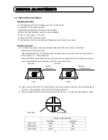
Raster position adjustment
Adjustment preparation
(1) Position adjustment
・・・
This will move an entire color.
Use this adjustment to match colors at the center of the screen.
(2) Use the buttons below to switch color to adjust.
[
▼
/ CH down] -Green
[0]
-Red
[
▲
/ CH up]
-Blue
Adjustment procedure
(1) Press the [SUB] button. Extra horizontal lines appear to confirm raster position mode.
(2) Use the cursor buttons to adjust position.
(3) Press [SUB] again for exit from raster position mode.
Notes :
①
Other functions cannot be accessed during the raster position adjustment mode.
Press [SUB] to exit from raster position mode, and confirm extra horizontal lines are disappeared.
②
Press [MENU] to switch between all colors displayed or adjustment color
and Green only.
Summary of Contents for C43-FD7000
Page 72: ...72 SERVICE ADJUSTMENTS SIGNAL SUB P W B IG02 IG03 IG04 IQ01 IQ02 IR01 Rear view IG01 I R 0 2 ...
Page 78: ...78 EXPLODED VIEW ...
Page 79: ...79 EXPLODED VIEW ...
Page 143: ......
Page 144: ......
Page 145: ......
Page 146: ......
Page 147: ......
Page 150: ......
Page 151: ......
Page 152: ......
Page 153: ......
Page 154: ......
Page 155: ......
Page 156: ......
Page 157: ......
Page 158: ......
Page 159: ......
Page 160: ......
Page 161: ......
Page 162: ......
Page 163: ......
Page 164: ......
Page 165: ......
Page 166: ......
Page 167: ......
Page 168: ......
Page 169: ......
Page 170: ...SIGNAL SIDE A P W B ...
Page 171: ...SIGNAL SIDE B P W B ...
Page 172: ...SIGNAL SUB SIDE A P W B ...
Page 173: ...SIGNAL SUB SIDE B P W B ...
Page 174: ...TUNER SIDE A P W B ...
Page 175: ...TUNER SIDE B P W B ...
Page 176: ...AUTO POWER AV INPUT CONVER SENSOR SW P W B ...
Page 177: ...CPT CONTROL AV NET LED P W B ...
Page 178: ...POWDEF P W B ...
Page 179: ......


