


43
SERVICE ADJUSTMENTS
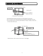
2.12 STATIC FOCUS ADJUSTMENT
Preparation for adjustment
(1)The raster inclination, centering, horizontal/vertical amplitude and optical/electrical focus and beam alignment
should be adjusted.
(2) The static convergence data should be cleared.
(3) Contrast control should be set MAX and Brightness control should be set Center.
(4) Receive the Hitachi circle pattern signal.
(5) Apply covers to the others then adjust lenses and project only single color on the screen.
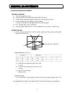
Adjustment procedure
(1) Red static focus adjustment.
Vary the static focus VR on Focus pack (UFPK) so that the right edge of Hitachi mark circle pattern is the
best clear. Check that the focus does not get conspicuously worse at other check point on the cross-hatch
signal.
(2) Blue static focus adjustment.
Vary the static focus VR on Focus pack (UFPK) so that the Hitachi mark on the circle pattern center is
the best clear. Check that the focus does not get conspicuously worse at all edges of the cross-hatch
signal.
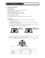
(3) Green static focus adjustment.
Vary the static focus VR on Focus pack (UFPK) (for green) so that the Hitachi mark on the circle pattern
center is the best clear. Check that the focus does not get conspicuously worse at checking point on
the picture periphery and the cross-hatch signal.
Remarks
Checking point for the periphery of picture.
Checking point
Summary of Contents for C43-FD7000
Page 72: ...72 SERVICE ADJUSTMENTS SIGNAL SUB P W B IG02 IG03 IG04 IQ01 IQ02 IR01 Rear view IG01 I R 0 2 ...
Page 78: ...78 EXPLODED VIEW ...
Page 79: ...79 EXPLODED VIEW ...
Page 143: ......
Page 144: ......
Page 145: ......
Page 146: ......
Page 147: ......
Page 150: ......
Page 151: ......
Page 152: ......
Page 153: ......
Page 154: ......
Page 155: ......
Page 156: ......
Page 157: ......
Page 158: ......
Page 159: ......
Page 160: ......
Page 161: ......
Page 162: ......
Page 163: ......
Page 164: ......
Page 165: ......
Page 166: ......
Page 167: ......
Page 168: ......
Page 169: ......
Page 170: ...SIGNAL SIDE A P W B ...
Page 171: ...SIGNAL SIDE B P W B ...
Page 172: ...SIGNAL SUB SIDE A P W B ...
Page 173: ...SIGNAL SUB SIDE B P W B ...
Page 174: ...TUNER SIDE A P W B ...
Page 175: ...TUNER SIDE B P W B ...
Page 176: ...AUTO POWER AV INPUT CONVER SENSOR SW P W B ...
Page 177: ...CPT CONTROL AV NET LED P W B ...
Page 178: ...POWDEF P W B ...
Page 179: ......


