background image

--- 17 ---

Fig. 9-1

Lamp [57]

Conector [59]

Brown

Blue

Conector [59]

Resistor (A) [47]

Switch [51]

Terminal [50]

Resistor [49]

Black

Red

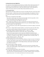
(2) Reassembly of the Gear [1]

(a) Apply grease (Hitachi Motor Grease No. 29) to the pinion and the meshing parts of the Gear [1], and also

to the inside of the metal of Inner Cover (B) [25].  5 Grams in total.

(b) When securing Inner Cover (A) [20] to Inner Cover (B) [25] with the Nylock Bolt (W/Flange) M4 x 12 [26],

be careful not to interfere with the rotation of the pinion.

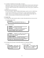
(3) Checking of operation after reassembly

(a) Check that the Knob [54] operates smoothly and the switch trigger can be locked and released reliably.

Check that the Lamp [57] is turned on when the Knob is operated.

(b) Check that the cutting and inclining operation of the Base Ass'y [46] is smoothly performed.

(c) Check that the Safety Cover [4] operates smoothly.

(d) Check that the brake is applied when turning off the switch.

(e) Check that the saw blade turns in the arrow direction indicated on the saw cover (counterclockwise viewed

from the front of the saw blade).

(f) Check that runout of the saw blade is 0.6 mm or less at 150 mm dia. position

(4) Wiring Diagram

Perform wiring as illustrated in Fig. 9-1 or 9-2.  Note that wrong wiring can cause troubles such as rotation

failure, inverse rotation and brake failure.

For the U.S.A. and Canada

Motor (B) [19]

Summary of Contents for C 6DC

Page 1: ...POWER TOOLS TECHNICAL DATA AND SERVICE MANUAL CORDLESS CIRCULAR SAW C 6DC SPECIFICATIONS AND PARTS ARE SUBJECT TO CHANGE FOR IMPROVEMENT LIST No F831 Apr 1999 C MODEL C 6DC ...

Page 2: ...AND SERVICE MANUAL a symbol s is are used in the place of company name s and model name s of our competitor s The symbol s utilized here is are as follows Symbols Utilized Competitors Company Name Model Name T DEWALT DW936K C MAKITA 5620DWA ...

Page 3: ...E CHARGE 6 8 PRECAUTIONS IN SALES PROMOTION 7 8 1 Handling Instructions 7 8 2 Caution Plates 8 8 3 Inherent Drawbacks of Cordless Circular Saws Requiring Particular Attention During Sales Promotion 9 Service Section 9 REPAIR GUIDE 10 9 1 Precautions in Disassembly and Reassembly 10 9 2 Precautions in Disassembly and Reassembly of Battery Charger 18 9 STANDARD REPAIR TIME UNIT SCHEDULES 19 Appendix...

Page 4: ...lade even at an angle of 45 This feature is expected to make this product series stand out from the existing competitive models Accordingly significant sales promotion and market share increases are anticipated 3 APPLICATIONS Cutting various wood materials 4 SELLING POINTS High capacity 2 0 Ah battery Off lock switch lever Convenient electric brake High strength Scratch resistant Ni plated cast al...

Page 5: ...w The shape angle and location of the Model C 6DC s switch handle is similar to those of AC powered circular saws that are familiar to users because of Hitachi s unique design of the battery holder The figures and the table below give a comparison of switch handles between the Model C 6DC and maker C s saw Cutting depth maximum Cutting depth 15 mm 5 8 C 6DC C dotted line C 15 C 6 D C 3 2 5 A C p o...

Page 6: ...s long as the switch trigger is depressed 3 The off lock switch lever automatically returns to off position and the spotlight is turned off when the trigger switch is released Switch trigger Off lock switch lever also used for a light switch The off lock switch lever and the light switch are integrated into one switch 5 90 Fine adjustment screw underneath the base The Model C 6DC is equipped with ...

Page 7: ...el UC 24YF Overcharge prevention circuit A built in electronic circuit detects the output voltage or surface temperature of the storage battery and automatically turns off the unit of prevent overcharge Before charging While charging Charging complete Charging impossible Charging impossible Indications of the pilot lamp Main body including battery 3 3 kg 7 3 lbs Charger unit including cord 1 kg 2 ...

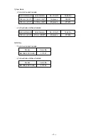
Page 8: ... pieces 302407 165 mm 6 1 2 15 9 mm 5 8 40 pieces 317451 For Australia and New Zealand External diameter Hole diameter No of teeth Code No 165 mm 6 1 2 20 mm 25 32 40 pieces 317452 2 Battery For America and Canada Model Code No EB 18B 2 000 mAh 317327 For Australia and New Zealand Model Code No EB 18B 2 000 mAh 317326 ...

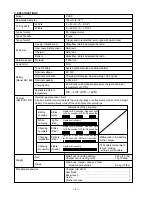
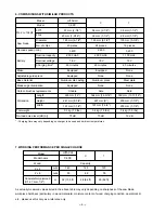
Page 9: ...0 minutes Equipped None Aluminum press None Able 364 mm 14 5 16 227 mm 9 197 mm 7 3 4 3 4 kg 7 5 lbs 75 dB T 38 mm 1 1 2 28 mm 1 1 8 135 mm 5 3 8 16 pieces 3 200 1 700 mAh 18 V 60 minutes None None Steel plate None Able 350 mm 13 13 16 200 mm 7 7 8 200 mm 7 7 8 3 4 kg 7 5 lbs 76 dB Charging time may vary depending on charger to be used and ambient temperatures 7 WORKING PERFORMANCE PER SINGLE CHAR...

Page 10: ...rmer etc between the power source and the charger If the charge is used with voltage over and above that indicated on the unit it will not function properly 5 Conduct battery charging at an ambient temperature range of 0 40 C 32 104 F Special temperature sensitive devices are employed in the charger to permit rapid charging Ensure that customers are instructed to use the charger at the indicated a...

Page 11: ...al of the Model EB 18B battery Ensure that all customers understand that Model EB 18B Batteries should be turned in to a Hitachi Power Tool sales outlet or authorized service center when they are no longer capable of being recharged or repaired If thrown into a fire the batteries may explode or if discarded indiscriminately leakage of the cadmium compound contained in the battery may cause environ...

Page 12: ...t perform heavy duty operations continuously 3 Do not place any foreign substance in the vent hole of the main body The outer body of this unit is provided with a vent hole for greater cooling efficiency Since the motor has a built in cooling fan a foreign substance inserted into the vent hole is likely to cause mechanical failure Instruct your customer never to cover or block the vent hole 4 Off ...

Page 13: ...nd the circled numbers in the following figures correspond to the item numbers in the parts list and the exploded assembly diagram for the Model C 6DC 9 1 1 Disassembly 1 Removal of the Saw Blade 11 While pressing the Lock Lever 23 turn the Bolt M7 x 17 5 13 clockwise with the attached Box Wrench 10 mm 503 to fix the saw blade shaft Turn the Bolt 13 counterclockwise with the Box Wrench 503 to loos...

Page 14: ...ck Flat Hd Screws M3 x 12 8 and then the Bearing Cover 7 Remove the Return Spring 5 from the Saw Cover 28 Remove the Safety Cover 4 from the Bearing Holder 2 3 Removal of the Saw Cover 28 Remove the Bolt Ass y Square M6 x 22 42 Remove the Tapping Screw W Flange D5 x 50 30 and then the Saw Cover 28 ...

Page 15: ...ew M5 x 12 3 to remove the Bearing Holder 2 and the Gear 1 Remove the Gear 1 from the Bearing Holder 2 b Remove Inner Cover A 20 B 25 and Motor B 19 from the Housing 32 Remove the Nylock Bolt W Flange M4 x 12 26 to remove Inner Cover B 25 c Remove the Lock Lever 23 and the Spring 33 then remove the Ball Bearing 24 from the pinion of the Motor B 19 Remove the two Machine Screws M5 x 10 22 to remove...

Page 16: ... 13 Fig 5 46 43 32 6 Removal of the Base Ass y 46 Extract the Roll Pin D6 x 45 43 that connects the Base Ass y 46 and the Housing 32 Remove the Base Ass y 46 ...

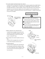
Page 17: ...y Reassembly can be accomplished by following the disassembly procedures in reverse with some items to be noted as follows 1 Reassembly of the components for power supply a Be sure to perform wiring connections as indicated in the wiring diagram Fig 9 1 or 9 2 For the U S A and Canada ...

Page 18: ... 62 63 64 61 60 59 57 58 47 48 49 51 17 18 19 Fig 7 19 20 For Australia and New Zealand b Mount Inner Cover A 20 to Motor B 19 as illustrated in Fig 7 Adjust the screw boss of Inner Cover A 20 to the hole of Motor B 19 ...

Page 19: ...into the groove Fig 8 2 51 Red Blue Black Terminal No 1 Convex 54 53 52 49 17 19 47 59 63 57 58 A A A A Brown Terminal No 2 Terminal No 3 Blue Black Yellow Terminal No 1 Convex c Connect the internal wires as illustrated in Figs 8 1 and 8 2 Mount the Knob 54 Terminal A 53 and Spring F 52 without fail For the U S A and Canada For Australia and New Zealand After putting 54 knob s convex in the hole ...

Page 20: ...and the switch trigger can be locked and released reliably Check that the Lamp 57 is turned on when the Knob is operated b Check that the cutting and inclining operation of the Base Ass y 46 is smoothly performed c Check that the Safety Cover 4 operates smoothly d Check that the brake is applied when turning off the switch e Check that the saw blade turns in the arrow direction indicated on the sa...

Page 21: ...ew M5 x 10 22 20 5 kg cm Tapping Screw W Flange D4 x 16 56 20 5 kg cm Tapping Screw D4 x 10 18 20 5 kg cm Seal Lock Flat Hd Screw M5 x 12 3 35 7 kg cm Seal Lock Flat Hd Screw M3 x 12 8 8 2 kg cm Nylock Bolt W Flange M4 x 12 26 35 7 kg cm 9 2 Precautions in Disassembly and Reassembly of Battery Charger Refer to the Technical Data and Service Manual of the Model UC 24YF Charger for precautions in di...

Page 22: ...20 30 40 50 60 min Fixed Variable C 6DC Work Flow Switch Socket Saw Blade Safety Cover Return Spring Inner Cover B Ball Bearing 609VV Inner Cover A Lock Lever Saw Cover Gear Bearing Holder Ball Bearing 6002VV Housing Motor B General Assembly Base Ass y ...

Page 23: ... 20 Assembly Diagram for C 6DC ...

Page 24: ...OVER A 1 21 949 454 SPRING WASHER M5 10 PCS 2 22 949 236 MACHINE SCREW M5X10 10 PCS 2 23 317 194 LOCK LEVER 1 24 609 VVM BALL BEARING 609VVMC2PS2S 1 25 317 195 INNER COVER B 1 26 317 196 NYLOCK BOLT W FLANGE M4X12 2 27 302 012 NUT M5 BLACK 1 28 317 201 SAW COVER 1 29 HITACHI LABEL 1 30 317 449 TAPPING SCREW W FLANGE D5X50 3 31 LABEL A 1 32 317 462 HOUSING 1 33 961 803 SPRING 1 34 310 842 CUSHION 1...

Page 25: ...4 299 KNOB 1 55 317 463 HANDLE COVER 1 56 305 812 TAPPING SCREW W FLANGE D4X16 BLACK 5 57 315 229 LAMP 12V 5W 1 58 317 212 SOCKET 1 59 959 141 CONNECTOR 50092 10 PCS 2 60 958 715 TAPPING SCREW D4X10 2 61 996 118 HOLDER SPRING 2 62 317 458 TERMINAL 1 63 308 037 TERMINAL PIECE 1 64 317 214 TERMINAL 1 65 317 326 BATTERY EB 18B W ENGLISH N P 1 65 317 327 BATTERY EB 18B W ENGLISH N P 1 FOR USA CAN ...

Page 26: ...23 12 98 Printed in Japan 981220 N STANDARD ACCESSORIES C 6DC ITEM NO CODE NO DESCRIPTION NO USED REMARKS 501 CHARGER MODEL UC 24YF 1 502 302 756 GUIDE 1 503 940 543 BOX WRENCH 10MM 1 504 317 218 CASE 1 ...

Reviews: