


--- 16 ---
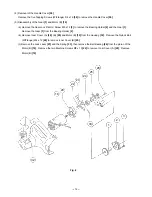
Fig. 8-1
59
50
51
54
53
52
49
17
57
58
A --- A
A
A
19
47
59
63
Plus side
Brown
Red
Brown
Terminal No.2
Terminal No.3
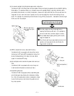
After putting 54 knob's "convex" in the hole of terminal (A),
assemble into the housing.
Insert the lead wire into the groove.
Insert the groove portion of the terminal into the rib of
the housing.
Insert the leadwire into the groove.
Fig. 8-2
51
Red
Blue
Black
Terminal No.1
Convex
54
53
52
49
17
19
47
59
63
57
58
A --- A
A
A
Brown
Terminal
No.2
Terminal
No.3
Blue
Black
Yellow
Terminal No.1
Convex
(c) Connect the internal wires as illustrated in Figs. 8-1 and 8-2. Mount the Knob [54], Terminal (A) [53] and
Spring (F) [52] without fail.
For the U.S.A. and Canada
For Australia and New Zealand
After putting 54 knob's "convex" in the hole
of terminal (A), assemble into the housing.
Insert the leadwire into the groove.
Insert the lead wire into the groove.
Plus side
Brown


