background image

AX-F300

–3

5–

–3

6–

–3

7–

Summary of Contents for AXF300E

Page 1: ... och skyddsanordningen felar eller satts ur funktion förekommer osynlig laserstrålning När apparaten öppnats och skyddsanordningen felar eller satts ur funktion förekommer osynlig laserstrålning När apparaten öppnats och skyddsanordningen felar eller satts ur funktion förekommer osynlig laserstrålning När apparaten öppnats och skyddsanordningen felar eller satts ur funktion förekommer osynlig lase...

Page 2: ...ed part Insulation tester DC 500V SAFETY PRECAUTIONS SAFETY PRECAUTIONS SAFETY PRECAUTIONS SAFETY PRECAUTIONS SAFETY PRECAUTIONS The following precautions should be observed when servicing 1 Since many parts in the unit have special safety related characteristics always use genuine Hitachi s replacement parts Especially critical parts in the power circuit block should not be replaced with other ma...

Page 3: ...240 V 50 60 Hz Power consumption 12 W Maximum external dimensions 210 W 96 5 H 340 D mm including feet controls and terminals Weight 3 2 kg SPEAKER HS R30 System 2 way BASS Reflex Speaker System Woofer 10 cm 1 Tweeter 5 cm 1 Impedance 6 ohms Maximum external dimensions 150 W 275 H 227 D mm Weight 3 0 kg 1 speaker TIMER System Digital Quartz Clock Display Format 12 hour cycle UC DEST 24 hour cycle ...

Page 4: ...emove 5 screws from the rear plate 2 Removal of Front Panel 1 Remove 4 screws from the bottom side of the front panel 2 Remove 2 screws from both sides 3 Remove screw to remove the ground wire E DEST ONLY 4 Remove the connectors and 5 Remove the Front Panel by releasing the pawl on both sides Pawl Pawl E DEST ONLY ...

Page 5: ...e knob assy remove the nut and remove the volume P W board 3 Remove 9 screws 5 Removal of Main P W Board 1 Lift up the TU P W board and remove it from the main P W board 2 Remove 2 screws from the top side of the main P W board 3 Remove 4 screws from the bottom side of the chassis 4 Remove the 4 P W board holders from the chassis via the bottom side of the chassis TU P W board Control Nut ...

Page 6: ...e rear panel 2 Removal of Front Panel 1 Remove 2 screws from both sides 2 Remove 3 screws from the bottom side of the front panel 3 Remove the Front Panel by releasing the pawl on both sides 4 Remove the flat cable from the main P W board 3 Removal of Rear Panel 1 Remove 7 screws from the rear panel Pawl Pawl ...

Page 7: ...ectors and of the main P W board 5 Remove the connector of the P T P W board 6 Remove 1 screw from the top side of the P T cover and detach the power transformer from the chassis 7 Remove 1 screw of the ground wire 8 Remove the connectors and of the motor P W board from the main P W board 9 Remove 2 screws from the motor P W board 10 Remove the solder from the four places of the soldering section ...

Page 8: ...ar panel 2 Removal of Front Panel 1 Remove 2 screws from both sides 2 Remove 4 screws from the bottom side of the front panel 3 Remove the Front Panel by releasing the pawl on both sides 4 Remove the flat cable from the main P W board 3 Removal of Rear Panel 1 Remove 7 screws from the rear panel FLAT C A B L E Pawl Pawl ...

Page 9: ...echanical Unit Assembly 1 Remove 4 screws 2 Remove the flat cable from the main P W board 5 Removal of Main P W Board 1 Lift up the I O P W board and remove if from the main P W board 2 Remove 6 screws FLAT C A B L E I O P W Board ...

Page 10: ...ng setting may result in damage of power transistors 1 Power switch OFF 2 Volume knob MIN 3 Function switch AUX 4 Speaker Open 5 VR502L R Minimum 1 Idle Current Adjustment 1 Connect the DC voltmeter to PG502 Refer to the connection diagram 2 Turn on the power and adjust VR502L on the left and VR502R on the right so that the measured value of the voltme ter can be within the range of 2 0 5 mV PRE A...

Page 11: ...10A P9A P8B CN505 P4A P6A CN505 P2A PG003 PG002 MAIN PWB PG504 CN502A CN501A CN101B PG402 CN103B CN104B PG301 P4 B P7A P5A P3B CN002 CN003 P10B P9B P8B P5B P6B P7B PT PWB CN104A CN103A W415 W001 DISP PWB CN101A TU PWB CN502B CN501B PG503 CN503 CN401 CN402 VO LUME PWB PG401 TONE PWB LUG TERMINAL LUG TERMINAL CN301 PRE AMP PWB AC CORD W101 AP1 W003 BLUE W005 ORG W009 RED ...

Page 12: ...TEM CONN 8P BTEM CONN 1 1 BLK 1 W101 29P FFC CABLE PG403 PG402 6P MX CONN 8P PH CONN 7P PH CONN 2P TXL CONN 1 1 1 5P PH CONN 5P TXL CONN PG404 W401B W402B W403B W401 BRN W402 YEL W403 RED W403A W402A W401A CN401 PG001 PT PWB VIDEO PWB W WUN ONLY VOL SEL PWB W WUN ONLY VIDEO MODULE W WUN ONLY AC CORD 1 BRN CN901 WN WUN ONLY 4P TXL CONN W WUN ONLY 1 PG421 1 AP1 5P MX CONN 6P MX CONN 3 DISC CHANGER S...

Page 13: ...AX F300 MINI DISC RECORDER HMD R50 PG002 AC CORD PG001 PG301 CN301 B to B CN501A CN1501 CN701B PG101 CN401 073 28P FFC CABLE W201 RED WHT CN002 1 CN002 2 CN101 PTPWB MAINPWB MDMECHAUNIT I O PWB CN701A FLPWB ...

Page 14: ... 14 AX F300 PRINTED WIRING BOARDS AM FM TUNER AMPLIFIER HTA R100 MAIN PWB Component Side ...

Page 15: ... 15 AX F300 Soldering Side ...

Page 16: ... 16 AX F300 PRE AMP PWB Component Side Soldering Side PT PWB Component Side Soldering Side ...

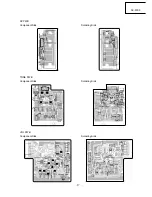
Page 17: ... 17 AX F300 SP PWB Component Side Soldering Side TONE PWB Component Side Soldering Side VOL PWB Component Side Soldering Side ...

Page 18: ... 18 AX F300 DISPLAY PWB TU PWB Soldering Side Component Side Soldering Side Component Side ...

Page 19: ... 19 AX F300 CD CHANGER DA R100 MAIN PWB Soldering Side Component Side FL PWB Soldering Side Component Side ...

Page 20: ... 20 AX F300 MONITOR PWB PT PWB Component Side Soldering Side Soldering Side Component Side ...

Page 21: ... 21 AX F300 MINI DISC RECORDER HMD R50 MAIN PWB Component Side ...

Page 22: ... 22 AX F300 Soldering Side ...

Page 23: ... 23 AX F300 DISPLA Y PWB Component Side Soldering Side ...

Page 24: ... 24 AX F300 I O PWB Component Side Soldering Side POWER PWB Component Side Soldering Side Component Side Soldering Side ...

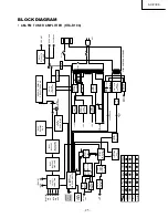
Page 25: ...PROM FL DISPLAY BL1 MW RF BLOCK BL1 MW LW RF BLOCK FE101 TUNER PACK FM RF AM LOOP AMP FM ANT Q102 2SK161 Q103 2SC2058S FM IF AMP Q153 DTA114EK Q151 Q152 DIC114TK Q514 LW MW SWITCH IC101 LC72131M PLL IC201 LA1838 AM RF FM IF MULTIPLEXER IC251 LC72720NM RDS DEMODULATOR UNIERSAL WUN ASIA W UK EBS EUROPE E USA UC 1 2 2 1 1 IC251 IC261 BL1 Q151 Q154 DEST SYM NO IC261 TA2040F AM STERO TO DISPLAY IC002 K...

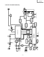
Page 26: ...RD DVK020 IC451 MOTOR DRIVER LB1648 IC451 µ CON MN1874823 IC102 DSP MN662720RB IC301 DAC PCM1725U IC302 AUDIO BA15218F CD MUTE 6V 5V 5V Ð 5V TRS SW IC101 PRE AMP AN8808SB LASER DRIVE 3 3V 5V SW105 SW106 SW107 SW108 MIC VOLUME SW103 SW104 CAM MOTOR NTSC PAL SW TRAY MOTOR M M Q302L R DTC323TK A MUTE TO DRIVER TO µ CON B1 B2 D401 IN4002 D403 IN4002 PR401 ICP N5 BISTAB 2SB647 C402 220 50 CE M D402 IN4...

Page 27: ...1 IC502 TC74HCU04AF IC502 TC74HCU04AF K60 K60 BUFFER Q661 IC403 TC74HC T04AF 3V 5V N G J 1 J 2 IC401 M30622MAA 855GP MICROCOMPUTER CO ERTER INPUT SELECT KEY IN BLOCK S710 IR701 REMOTE SENSOR LED D702 POWER ON Ind S701 706 S708 709 VOLTAGE REGULATOR 3V Q102 103 FL POWER CIRCUIT VOLTAGE REGULATOR IC 101 6V uPC2406AHF Q101 6V 5V FL DISPLAY FL VP 28V V VOLTAGE REGULATOR IC102 5V KIA 7805 F102 F101 P D...

Page 28: ... 28 AX F300 ...

Page 29: ...AX F300 29 30 31 CIRCUIT DIAGRAM AM FM TUNER AMPLIFIER HTA R100 ...

Page 30: ...AX F300 32 33 34 ...

Page 31: ...AX F300 35 36 37 ...

Page 32: ...AX F300 38 39 40 ...

Page 33: ...AX F300 41 42 43 CD CHANGER DA R100 ...

Page 34: ...AX F300 44 45 46 ...

Page 35: ...AX F300 47 48 49 MINI DISC RECORDER HMD R50 ...

Page 36: ......

Page 37: ... B A A A A B B PT001 MAIN PWB PRE AMP PWB DISPLAY PWB VOLUME PWB TU PWB AP1 Speaker Remote control 069 057 133 213 211 101 091 097 229 215 216 215 133 090 081 082 223 222 222 115 100 100 111 113 221 210 214 213 224 105 111 UC 102 E BS 103 W UN 051 UC 052 E BS 053 W UN 215 094 095 UC ...

Page 38: ... MAIN PWB AP1 W WUN FL PWB MOTOR PWB PT PWB PT001 056 056 064 071 211 211 081 090 089 088 217 222 221 213 221 229 052 051 229 216 116 086 096 098 220 219 212 103 102 111 070 099 217 217 217 105 217 218 217 225 214 215 W WUN W WUN UC E EBS UC E EBS W WUN 069 074 ...

Page 39: ... B MAIN PWB PT001 AC OUTLET E EBS EBS ONLY E EBS AC OUTLET UC UC W WUN AP1 Voltage Selector P W B FL DISP PWB I O PWB 39 37 69 57 23 41 35 31 33 90 103 103 71 98 91 53 72 74 55 98 73 91 51 59 67 92 68 70 104 104 99 102 67 54 52 30 1 701 93 61 96 94 61 66 101 101 201 21 25 56 92 ...

Page 40: ...THE UPDATED PARTS LIST FOR THIS MODEL IS AVAILABLE ON ESTA ...

Page 41: ...l 39 02 487861 Tel 39 02 38073415 Servizio Clienti Fax 39 02 48786381 2 Email customerservice italy hitachi eu com HITACHI HOME ELECTRONICS NORDIC AB Box 77 S 164 94 Kista SWEDEN Tel 46 0 8 562 711 00 Fax 46 0 8 562 711 13 Email csgswe hitachi eu com HITACHI EUROPE S A S Lyon Office B P 45 69671 BRON CEDEX FRANCE Tel 04 72 14 29 70 Fax 04 72 14 29 99 Email france consommateur hitachi eu com HITACH...

Reviews: