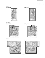
– 7 –
AX-F300
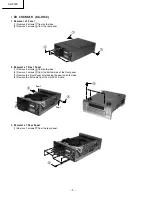
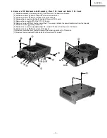
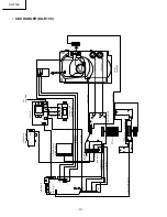
4. Removal of CD Mechanical-Unit Assembly, Main P. W. Board and Motor P. W. Board
(1) Remove one each of screws
and
from the main P. W. board on the side.
(2) Remove 2 screws
from the top side of the mechanical unit.
(3) Remove 2 screws
from the bottom side of the chassis.
(4) Remove the connectors
,
,
and
of the main P. W. board.
(5) Remove the connector
of the P. T. P. W. board.
(6) Remove 1 screw
from the top side of the P. T. cover and detach the power transformer from the chassis.
(7) Remove 1 screw
of the ground wire.
(8) Remove the connectors
,
and
of the motor P. W. board from the main P. W. board.
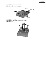
(9) Remove 2 screws
from the motor P. W. board.
(10) Remove the solder from the four places of the soldering section
of the motor.
(11) Remove the connectors PG402 and 403 of the motor P. W. board.
PG402
PG403
Summary of Contents for AXF300E
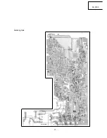
Page 14: ... 14 AX F300 PRINTED WIRING BOARDS AM FM TUNER AMPLIFIER HTA R100 MAIN PWB Component Side ...
Page 15: ... 15 AX F300 Soldering Side ...
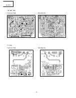
Page 16: ... 16 AX F300 PRE AMP PWB Component Side Soldering Side PT PWB Component Side Soldering Side ...
Page 18: ... 18 AX F300 DISPLAY PWB TU PWB Soldering Side Component Side Soldering Side Component Side ...
Page 20: ... 20 AX F300 MONITOR PWB PT PWB Component Side Soldering Side Soldering Side Component Side ...
Page 21: ... 21 AX F300 MINI DISC RECORDER HMD R50 MAIN PWB Component Side ...
Page 22: ... 22 AX F300 Soldering Side ...
Page 23: ... 23 AX F300 DISPLA Y PWB Component Side Soldering Side ...
Page 28: ... 28 AX F300 ...
Page 29: ...AX F300 29 30 31 CIRCUIT DIAGRAM AM FM TUNER AMPLIFIER HTA R100 ...
Page 30: ...AX F300 32 33 34 ...
Page 31: ...AX F300 35 36 37 ...
Page 32: ...AX F300 38 39 40 ...
Page 33: ...AX F300 41 42 43 CD CHANGER DA R100 ...
Page 34: ...AX F300 44 45 46 ...
Page 35: ...AX F300 47 48 49 MINI DISC RECORDER HMD R50 ...
Page 36: ......
Page 40: ...THE UPDATED PARTS LIST FOR THIS MODEL IS AVAILABLE ON ESTA ...

