background image

33

USING THE REMOTE TO CONTROL
SET-TOP-BOX/SATELLITE RECEIVER FUNCTIONS

Operating the precoded function for your satellite receiver.

This remote is designed to operate different types of set-top-box/satellite systems. You must first program the remote to match  the
remote system of your set-top-box/satellite receiver.  (refer to page 36)

1.

Turn ON your set-top-box/satellite receiver.

2.

Aim the remote control at the front of your set-top-box/satellite receiver.

3.

Press and release the SET-TOP-BOX (STB) button to switch to set-top-box/satellite pre-coded mode.

4.

Hold down the STB button on the remote and enter the two digit preset code that matches your set-top-box/satellite receiver as
shown on page 36.  The indicator light will flash 3 times if the code was accepted.

5.

Aim the remote at the set-top-box/satellite receiver and press the OFF button.  The remote will turn off your set-top-box/satellite
receiver when the correct two digit preset code is entered.  When this occurs, the remote control is programmed for your set-top-
box/satellite receiver.  If the set-top-box/satellite receiver does not turn off, try a different two digit preset code.

6.

The remote will now control your set-top-box/satellite receiver.

NOTES:

1.

If your set-top-box/satellite receiver cannot be operated
after performing the above procedures, your set-top-
box/satellite receiver code has not been precoded into the
remote.

2.

In the unlikely event that your set-top-box/satellite
receiver cannot be operated after performing the above
procedures, please consult your set-top-box/satellite
receiver operating guide.

3.

The remote control will remember the codes you have
programmed until the batteries are removed from the
remote control.  After replacing the batteries repeat the
entire programming procedure as stated above.

4.

The ANT button will act as the TV/STB button when in
STB mode.

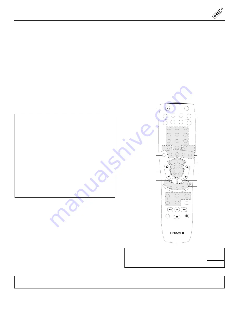
SET-TOP-BOX (STB) button

This button allows the remote to control your set-top-
box/satellite receiver by setting it to SET-TOP-
BOX/SATELLITE mode.

PRECODED SET-TOP-BOX/SATELLITE RECEIVER buttons

These buttons transmit the chosen precoded satellite codes.

EXCLUSIVE TV buttons

These buttons are for operating the TV.

ON

TV

VCR

CBL

TAPE

CD

AMP

STB

DVD

1

2

4

5

6

3

7

8

9

0

LAST CH

SLEEP

ANT

HELP

C.S.

EXIT

MENU

CH

VOL

STATUS

MUTE

GUIDE/TV

GUIDE/TV

GUIDE/TV

INFO

VCR PLUS+

SVCS

GUIDE/TV

SCHD

PIP

PIP CH

SWAP

FREEZE

PIP MODE

PIP ACCESS

PROG

TV/VCR

SLOW

SOURCE WIZARD

REC

SELECT

TV/PC

ASPECT

OFF

VID1

VID2

VID3

CLU-5715TSI

MY SET-TOP-BOX/

SATELLITE CODE IS:

NOTE:

Refer to instruction manual of the Set-Top-Box/Satellite Receiver for operation of the buttons exclusively for the Set-Top-
Box/Satellite Receiver.

Summary of Contents for 55DMX01WD

Page 1: ...T TIME USE 4 23 THE REMOTE CONTROL 24 36 ULTRATEC BIT MAP ON SCREEN DISPLAY LAMP REPLACEMENT PLUG AND PLAY TRADEMARK ACKNOWLEDGMENT AGENCY REGULATORY INFORMATION USEFUL INFORMATION SPECIFICATIONS SERVICE HOTLINE FEATURE INFORMATION 79 90 68 78 37 67 Digital Light Processing DLP Digital Micromirror Device and DMD are trademarks of Texas Instruments The DLP logo is a trademanrk of Texas Instruments ...

Page 2: ...erature accompanying the appliance WARNING TO PREVENT FIRE OR SHOCK HAZARD DO NOT EXPOSE THIS TELEVISION TO RAIN OR MOISTURE NOTE There are no user serviceable parts inside the color television Model and serial numbers are indicated on back side of the television This television is not intended for use in a computer room POWER SOURCE THIS TELEVISION IS DESIGNED TO OPERATE ON 120 VOLTS 60Hz AC CURR...

Page 3: ... 17 An outdoor antenna should not be located in the vicinity of overhead power lines or other electrical circuits 18 If an outside antenna is connected to the receiver be sure the antenna system is grounded so as to provide some protection against voltage surges and built up static charges Section 810 of the National Electric Code ANSI NFPA No 70 1984 provides information with respect to proper gr...

Page 4: ...5D 55V TELEVISION STAND Not included order separately OPTIONAL H530051 CUSTOM HITACHI TELEVISION STAND Excellent for VCR and video tape storage Special features include thick top shelf 1 inch aluminum column shark grey color glass shelf green edge and black rubber foot ON TV VCR CBL TAPE CD AMP STB DVD 1 2 4 5 6 3 7 8 9 0 LAST CH SLEEP ANT HELP C S EX IT MEN U CH VOL STATUS MUTE GUIDE TV GUIDE TV ...

Page 5: ...FF then ON again Three LEDs indicate the set is under power on condition On Three LED s blink alternately Off One LED blinks 4 When power off Fans will keep working for about 2 minutes after power OFF to cool down the lamp 5 Lamp replacement It is recommended that you replace the lamp every 4000 hours to obtain good picture bright ness This is not a guarantee that life time of a lamp is 4000 hours...

Page 6: ...a 75 Ohm coaxial cable system connect the outdoor antenna or CATV coaxial cable to the ANT A 75 Ohm terminal If you have a second antenna or cable TV system connect the coaxial cable to the ANT B terminal VHF 300 Ohm antenna UHF antenna When using a 300 Ohm twin lead from an outdoor antenna connect the VHF or UHF antenna leads to screws of the VHF or UHF adapter Plug the adapter into the antenna t...

Page 7: ...aler for proper part If light is blinking lamp cover is not assembled securely after replacement TEMP Indicator This light is off during normal operation If this indicator is lit the optic unit is too hot If this indicator is blinking the cooling fan has stopped Please call service Shown with Control Panel Door Closed LAMP TEMP POWER Push to open door for front controls and inputs DLP A TEXAS INST...

Page 8: ...ent antenna source VIDEO 1 2 3 or alternate antenna source Your selection is shown in the top right corner of the screen This button also serves as the EXIT button when in MENU mode MENU Button This button allows you to enter the MENU making it possible to set TV features to your preference without using the remote This button also serves as the SELECT button when in menu mode VOLUME Level Press t...

Page 9: ... VCR D SUB 15 Pin RGB Cable Optional PC AUDIO OUT Back of PC Audio Cable Optional S VHS Video Camera Output VIDEO 3 VOL AUDIO IN VIDEO 3 PC2 L MONO R VIDEO S VIDEO PC2 1 2 3 4 5 6 7 8 9 10 11 12 13 14 15 INPUT VOL CH CH TV PC EXIT MENU SELECT VIDEO 3 VOL AUDIO IN VIDEO 3 PC2 L MONO R VIDEO S VIDEO PC2 1 2 3 4 5 6 7 8 9 10 11 12 13 14 15 INPUT VOL CH CH TV PC EXIT MENU SELECT VIDEO 3 VOL AUDIO IN V...

Page 10: ... see page 65 Optical Input This jack provides high quality audio input from a Dolby Digital DVD player or HDTV Set Top Box Use a digital optical cable to connect your TV to a compatible device This input can be used for VIDEO 1 or VIDEO 2 audio as selected in the THEATER INPUT SOURCE menu see page 65 ANT A TO CONVERTER ANT B 1 2 3 4 5 6 7 8 9 10 11 12 13 14 15 AUDIO L R MONO VIDEO VIDEO AUDIO MONO...

Page 11: ...ween two separate 75 Ohm RF antenna inputs ANT A and ANT B ANT A input can be displayed as a main picture or sub picture ANT B can only be displayed as a main picture ANT B cannot be displayed as a sub picture The antenna output labeled TO CONVERTER allows the ANT A connection to pass directly to a different source such as a cable box only when ANT B is displayed as a main picture NOTE DO NOT conn...

Page 12: ...or COMPONENT Y PBPR inputs but note that only one of these may be used at a time Connect only 1 component to each input jack COMPONENT Y PBPR connections are provided for high performance components such as DVD players Use these connections in place of the standard video connection if your device has this feature When using the Y PBPR input jacks connect your components audio output to the TV s Le...

Page 13: ...I 2 Way signal splitter Outside antenna or cable TV coaxial cable 1 2 3 4 5 6 7 8 9 10 11 12 13 14 15 AUDIO OUT OPTIONAL VCR 2 V L R INPUT S VIDEO INPUT OUTPUT Cable TV Box Optional see tips on page 12 Laserdisc player VCR camcorder etc OUTPUT Y PB PR L R HDTV Set Top Box V L R OUTPUT S VIDEO Optional see tips on page 12 OR DVD Player VCR 1 ANT IN OUTPUT S VIDEO V L R OUTPUT Y PB CB PR CR L R OR R...

Page 14: ...negative lead wire Repeat this procedure for the Left Speaker TO EXTERNAL SPEAKER L R PROJECTION TV SPEAKER AMPLIFIER CAUTION Do not connect speakers simultaneously to the REAR SPEAKER terminal of the Rear Projection TV and an external amplifier This could damage both the TV and the speakers Your TV was designed to use 8 Ohm speakers only Any other type may degrade the audio performance of your en...

Page 15: ...AR SPEAKER 8Ω ONLY L R OPTICAL INPUT COAXIAL INPUT PC RGB INPUT 1 PC AUDIO INPUT 1 MONITOR OUT INPUT 2 INPUT 1 AUDIO TO HI FI INPUT Stereo System Amplifier R L To Audio Input Terminal of External Amplifier CONNECTING EXTERNAL AUDIO AMPLIFIER To control the audio level of an external audio amplifier with the remote control connect the system as shown below NOTE To prevent damage to the speaker and ...

Page 16: ... center channel speaker which is on only when the television is in SURROUND STADIUM SURROUND ROCK ARENA SURROUND JAZZ CLUB SURROUND PRO LOGIC or SURROUND DOLBY DIGITAL mode These speakers are connected to a separate audio amplifier Use the AUDIO TO HI FI output on the TV These speakers are connected to a rear speaker 8 Ohm output on the TV This sub woofer is connected to the SUB WOOFER output on t...

Page 17: ...d with a DVD player or HDTV Set Top Box with Dolby Digital output This provides up to 6 channels of all digital surround sound There are 3 full range channels for the front FL C FR plus separate full range left and right surround channels SL SR The sixth channel is Low Frequency Effects for a sub woofer SW supplying those room shaking rumbles experienced in the best movie theaters When left and ri...

Page 18: ... panel of the Rear Projection TV i e VCR laserdisc player etc is not connected or the video device is OFF the TV set will appear to be OFF CONNECTING A MONAURAL AUDIO VCR OR LASERDISC PLAYER 1 Connect the cable from the VIDEO OUT of the VCR or the laserdisc player to the INPUT VIDEO jack on the TV set below 2 Connect the cable from the AUDIO OUT of the VCR or the laserdisc player to the INPUT MONO...

Page 19: ...11 12 13 14 15 AUDIO L R MONO VIDEO VIDEO AUDIO MONO L R VIDEO S VIDEO Y S VIDEO Y B R P P B R P P S VIDEO L R L R SUB WOOFER STOP CONNECT ONLY 8 OHM SPEAKERS DO NOT SHORT CIRCUIT THESE TERMINALS Such damage is NOT COVERED by your television warranty REAR SPEAKER 8Ω ONLY L R OPTICAL INPUT COAXIAL INPUT Rear Panel of Television Hitachi Model or Similar Model Back of VCR R L V VCR OUTPUT PC RGB INPU...

Page 20: ... jacks The picture and sound that is played back will be abnormal if the connection is loose 2 A single VCR can be used for VCR 1 and VCR 2 but note that a VCR cannot record its own video or line output INPUT 1 in example on page 13 Refer to your VCR operating guide for more information on line input output connections ANT A TO CONVERTER ANT B 1 2 3 4 5 6 7 8 9 10 11 12 13 14 15 AUDIO L R MONO VID...

Page 21: ...serdisc DVD player or HDTV set top box The VIDEO icon disappears automatically after approximately eight seconds 7 Press the ANT button to return to the previous channel ANT A TO CONVERTER ANT B 1 2 3 4 5 6 7 8 9 10 11 12 13 14 15 AUDIO L R MONO VIDEO VIDEO AUDIO MONO L R AUDIO MONO L R VIDEO S VIDEO Y S VIDEO Y B R P P B R P P S VIDEO L R L R SUB WOOFER STOP CONNECT ONLY 8 OHM SPEAKERS DO NOT SHO...

Page 22: ...gs when connecting to rear panel jacks The picture and sound that is played back will be abnormal if the connection is loose 2 See page 12 for tips on REAR PANEL CONNECTIONS 3 If your device is connected to INPUT 1 component jacks make sure to select VID1 OPTICAL from the THEATER INPUT SOURCE menu If it is connected to INPUT 2 component jacks make sure to select VID2 OPTICAL from the THEATER INPUT...

Page 23: ... 15 AUDIO L R MONO VIDEO VIDEO AUDIO MONO L R AUDIO MONO L R VIDEO S VIDEO Y S VIDEO Y B R P P B R P P S VIDEO L R L R SUB WOOFER STOP CONNECT ONLY 8 OHM SPEAKERS DO NOT SHORT CIRCUIT THESE TERMINALS Such damage is NOT COVERED by your television warranty REAR SPEAKER 8Ω ONLY L R OPTICAL INPUT COAXIAL INPUT PC RGB INPUT 1 PC AUDIO INPUT 1 MONITOR OUT INPUT 2 INPUT 1 AUDIO TO HI FI Back of SET TOP B...

Page 24: ...eceiver and press the SET TOP BOX STB button The STB button will blink indicating that the remote will now control your set top box satellite receiver See page 33 for instructions on how to program the remote to control your set top box satellite receiver To operate your DVD player point the remote at the remote sensor of the DVD player and press the DVD button The DVD button will blink indicating...

Page 25: ...ink to indicate the remote is in CABLE mode see page 32 SET TOP BOX STB When the STB button is pressed it will blink to indicate the remote is in STB mode If you have a satellite receiver use this button to program your satellite receiver see page 33 DVD button When the DVD button is pressed it will blink to indicate the remote is in DVD mode see page 34 ON TV VCR CBL TAPE CD AMP STB DVD 1 2 4 5 6...

Page 26: ...ample the SET UP menu has 9 sub menu s Pressing the button while in the SET UP menu will take you directly to the CLOCK SET sub menu This makes navigating the menu s faster and easier NOTE The TV may not receive some channels if you are not in the correct SIGNAL SOURCE mode see page 41 ANT A 10 ANT A 39 LAST CH TV PC button Press this button to switch between TV PC1 PC INPUT 1 and PC2 PC INPUT 2 m...

Page 27: ...source if the channel has stereo ST or second audio program SAP the time CHANNEL ID if the Commercial Skip C S function is activated and if the SLEEP timer is set PICTURE IN PICTURE buttons See separate section on page 28 for a description PIP CH button Use the PIP CH button to select between main picture and sub picture tuning The channel number which is highlighted indicates what channel is bein...

Page 28: ...el tuning is for the main picture When the lower channel display is highlighted channel tuning is for the PIP sub picture This method of picture tuning is the same for one antenna input ANT A only and two antenna inputs ANT A and ANT B The Picture in Picture feature is convenient when you want to watch more than one program at the same time You can watch a TV program while viewing other programs f...

Page 29: ...es along the right edge of the screen Press the PIP button a second time to remove the sub pictures from the screen SWAP button If you wish to switch what is being shown on the main picture to the sub picture press the SWAP button ANT A 28 ANT A 10 VIDEO 1 09 10 12 PIP MODE button To change between the three different PIP modes SINGLE SPLIT or SURF press the PIP MODE button when PIP is ON Each pre...

Page 30: ... to normal viewing CAUTION A pattern burn may develop if the sub picture is left in the same corner permanently If the PIP feature is used frequently occasionally MOVE the sub picture using the THUMB STICK or NOTES 1 Each freeze frame is delayed about 0 1 1 10 second 2 When viewing a COMPONENT Y PBPR INPUT only SPLIT MODE FREEZE is allowed NOTE The FREEZE function will only operate when SINGLE PIP...

Page 31: ... event that your VCR cannot be operated after performing the above procedures please consult your VCR operating guide 3 The remote control will remember the codes you have programmed until the batteries are removed from the remote control After replacing the batteries repeat the entire programming procedure as stated above 4 The MENU button will act as the VCR MENU button for HITACHI VCRs 5 The LA...

Page 32: ...een precoded into the remote 2 In the unlikely event that your cable box cannot be operated after performing the above procedures please consult your cable box operating guide 3 The remote control will remember the codes you have programmed until the batteries are removed from the remote control After replacing the batteries repeat the entire programming procedure as stated above 4 The LAST CH but...

Page 33: ... set top box satellite receiver cannot be operated after performing the above procedures your set top box satellite receiver code has not been precoded into the remote 2 In the unlikely event that your set top box satellite receiver cannot be operated after performing the above procedures please consult your set top box satellite receiver operating guide 3 The remote control will remember the code...

Page 34: ...TES 1 If your DVD player cannot be operated after performing the above procedures your DVD player s code has not been precoded into the remote 2 In the unlikely event that your DVD player cannot be operated after performing the above procedures please consult your DVD player operating guide 3 The remote control will remember the codes you have programmed until the batteries are removed from the re...

Page 35: ...1 6 if you wish to program the remote to control another Audio Video component NOTES 1 If your Audio Video component cannot be operated after performing the above procedures your Audio Video component s code has not been precoded into the remote 2 In the unlikely event that your Audio Video component cannot be operated after performing the above procedures please consult your Audio Video equipment...

Page 36: ...Sony 02 Toshiba 05 Yamaha 08 Zenith 05 11 CABLE BRAND CODE ABC 01 07 08 17 18 20 36 37 49 Antronix 39 Archer 11 24 39 Belcor 32 Cable Star 32 Century 11 Citizen 11 Colour Voice 30 42 Comtronics 25 28 Contec 21 Dae Ryung 20 Eastern 14 Electricord 31 Everquest 51 Focus 52 Garrard 11 GC Electronics 32 39 Gemini 05 38 43 51 General Instrument 01 12 Goldstar 10 25 Hamlin 04 13 22 23 Hitachi 01 Hytex 36...

Page 37: ...ITACHI Projection TV 2 Press the THUMB STICK to highlight a different feature 3 Press EXIT on the remote control to quickly exit from a menu 4 Press HELP on the remote control when a menu is displayed and text will appear giving a description of that menu HELP EXIT MENU SELECT TO QUIT EXIT SETUP CUSTOMIZE VIDEO AUDIO THEATER 1 MENU LANGUAGE 2 PLUG PLAY 3 SIGNAL SOURCE 4 AUTO CHANNEL SET 5 CHANNEL ...

Page 38: ...d off once daily or weekly 6 AUTO LINK Automatically turn TV on with any VIDEO input 7 CLOSED CAPTION Feature to display dialogue text 8 MENU BACKGROUND Select from three types of backgrounds 1 CONTRAST Adjust contrast 2 BRIGHTNESS Adjust brightness 3 COLOR Adjust color 4 TINT Adjust tint 5 SHARPNESS Adjust sharpness 6 RESET Set VIDEO settings to factory preset 7 ADVANCED Improve picture performan...

Page 39: ...MATS 9 LAMP TIME MENU TO MENU BAR TO QUIT MENU TO MENU BAR TO QUIT MENU TO MENU BAR TO QUIT 1 MENU LANGUAGE ENGLISH 2 PLUG PLAY FRANCAIS 3 SIGNAL SOURCE ESPAÑOL 4 AUTO CHANNEL SET 5 CHANNEL MEMORY 6 CHANNEL LIST 7 CLOCK SET 8 PICTURE FORMATS 9 LAMP TIME SETUP CUSTOMIZE VIDEO AUDIO THEATER SETUP CUSTOMIZE VIDEO AUDIO THEATER SET UP EXIT MENU TO QUIT 1 MENU LANGUAGE 2 PLUG PLAY 3 SIGNAL SOURCE 4 AUT...

Page 40: ...ANTENNA OR CABLE WITHOUT CABLE BOX B CABLE BOX C SATELLITE RECEIVER D SATELLITE RECEIVER WITH CABLE BOX PRESS TO SELECT PRESS TO ENTER QUESTION 2 I WANT TO CONNECT A VCR DVD TO MY SYSTEM A YES B NO PRESS TO SELECT PRESS TO ENTER QUESTION 3 I WANT TO CONNECT A SET TOP BOX TO MY SYSTEM A YES B NO PRESS TO SELECT PRESS TO ENTER MENU TO MENU BAR TO QUIT EXIT MENU TO MENU BAR TO QUIT EXIT MENU TO MENU ...

Page 41: ...TUP CUSTOMIZE VIDEO AUDIO THEATER SETUP CUSTOMIZE VIDEO AUDIO THEATER SETUP CUSTOMIZE VIDEO AUDIO THEATER 1 MENU LANGUAGE 2 PLUG PLAY 3 SIGNAL SOURCE ANTENNA 4 AUTO CHANNEL SET CATV 1 5 CHANNEL MEMORY CATV 2 6 CHANNEL LIST 7 CLOCK SET 8 PICTURE FORMATS 9 LAMP TIME 1 MENU LANGUAGE 2 PLUG PLAY 3 SIGNAL SOURCE ANTENNA 4 AUTO CHANNEL SET CATV 1 5 CHANNEL MEMORY CATV 2 6 CHANNEL LIST 7 CLOCK SET 8 PICT...

Page 42: ...TO CHANNEL SET See CHANNEL MEMORY to add or to erase additional channels AUTO CHANNEL SET MENU TO MENU BAR TO QUIT EXIT MENU TO MENU BAR TO QUIT EXIT MENU TO MENU BAR TO QUIT EXIT AUTO CHANNEL SET 1 MENU LANGUAGE 2 PLUG PLAY 3 SIGNAL SOURCE 4 AUTO CHANNEL SET BEGIN 5 CHANNEL MEMORY 6 CHANNEL LIST 7 CLOCK SET 8 PICTURE FORMATS 9 LAMP TIME THUMB STICK THUMB STICK SETUP CUSTOMIZE VIDEO AUDIO THEATER ...

Page 43: ...TICK THUMB STICK 1 MENU LANGUAGE 2 PLUG PLAY 3 SIGNAL SOURCE CHANNEL 3 4 AUTO CHANNEL SET ADD 5 CHANNEL MEMORY ERASE 6 CHANNEL LIST 7 CLOCK SET 8 PICTURE FORMATS 9 LAMP TIME 1 MENU LANGUAGE 2 PLUG PLAY 3 SIGNAL SOURCE CHANNEL 3 4 AUTO CHANNEL SET ADD 5 CHANNEL MEMORY ERASE 6 CHANNEL LIST NEXT CH 7 CLOCK SET CH CH 8 PICTURE FORMATS OR KEYS 9 LAMP TIME 1 MENU LANGUAGE 2 PLUG PLAY 3 SIGNAL SOURCE CHA...

Page 44: ...4 CBS ON 5 6 CNN ON 7 COM ON ON 8 ESP2 ON CHANNEL LIST ANT A CH ID SCAN LOCK 9 HBO ON 10 HGTV ON 11 FOX ON 12 BET ON 13 AMC ON 14 HSN ON ON 15 16 FAM ON MENU TO MENU BAR TO QUIT EXIT MENU TO MENU BAR TO QUIT EXIT MENU TO MENU BAR TO QUIT EXIT THUMB STICK THUMB STICK SETUP CUSTOMIZE VIDEO AUDIO THEATER 1 MENU LANGUAGE 2 PLUG PLAY 3 SIGNAL SOURCE 4 AUTO CHANNEL SET 5 CHANNEL MEMORY 6 CHANNEL LIST 7 ...

Page 45: ...ious menu when the CURSOR is in the first position CLOCK SET CLOCK SET AM JAN 01 2000 CLOCK SET 12 00 PM MAY 10 2000 MENU TO MENU BAR TO QUIT EXIT MENU TO MENU BAR TO QUIT EXIT TO SET TIME THUMB STICK TO SET TIME MENU TO MENU BAR TO QUIT EXIT SETUP CUSTOMIZE VIDEO AUDIO THEATER SETUP SETUP 1 MENU LANGUAGE 2 PLUG PLAY 3 SIGNAL SOURCE 4 AUTO CHANNEL SET 5 CHANNEL MEMORY 6 CHANNEL LIST 7 CLOCK SET 8 ...

Page 46: ...NU BAR TO QUIT EXIT THUMB STICK PRESS SELECT TO ACTIVATE DEACTIVATE PRESS SELECT TO ACTIVATE DEACTIVATE PICTURE FORMATS ANT A 3 ASPECT STYLE NORMAL FULL FILL SMOOTH WIDE V POSITION 0 V SIZE 15 COMPONENT COLOR TYPE HDTV SDTV DVD 1 MENU LANGUAGE 2 PLUG PLAY 3 SIGNAL SOURCE 4 AUTO CHANNEL SET 5 CHANNEL MEMORY 6 CHANNEL LIST 7 CLOCK SET 8 PICTURE FORMATS 9 LAMP TIME SETUP SETUP SELECT Normal Choose th...

Page 47: ...ll three video inputs have independent Aspect Style settings 2 You will not be able to access the V Position menu if Aspect Style Normal is set 3 You will not be able to access the V SIZE menu if Aspect Style Normal or Full is set 4 You will only be able to access the Aspect Style menu when viewing a 4 3 480i or 480P When viewing a 16 9 1080i or 720P input you will not be able to access this menu ...

Page 48: ...U TO MENU BAR TO QUIT EXIT PRESS SELECT TO ACTIVATE DEACTIVATE LAMP TIME 15 H RESET LAMP TIME 15 H RESET ARE YOU SURE SETUP 1 MENU LANGUAGE 2 PLUG PLAY 3 SIGNAL SOURCE 4 AUTO CHANNEL SET 5 CHANNEL MEMORY 6 CHANNEL LIST 7 CLOCK SET 8 PICTURE FORMATS 9 LAMP TIME SETUP CUSTOMIZE VIDEO AUDIO THEATER At around 4 000 hours of operations the lamp needs to be replaced with a new one There is a spare lamp ...

Page 49: ...EL ID NOTES 1 If ANT A and ANT B are in the same SIGNAL SOURCE mode see page 41 the CHANNEL ID for both antenna inputs will be the same 2 CHANNEL ID will be displayed only when channel is displayed as main picture CHANNEL ID MENU TO MENU BAR TO QUIT EXIT MENU TO MENU BAR TO QUIT EXIT MENU TO MENU BAR TO QUIT EXIT MENU TO MENU BAR TO QUIT EXIT MENU TO MENU BAR TO QUIT EXIT MENU TO MENU BAR TO QUIT ...

Page 50: ...yed only when VIDEO input is displayed as main picture VIDEO ID MENU TO MENU BAR TO QUIT EXIT MENU TO MENU BAR TO QUIT EXIT MENU TO MENU BAR TO QUIT EXIT MENU TO MENU BAR TO QUIT EXIT MENU TO MENU BAR TO QUIT EXIT MENU TO MENU BAR TO QUIT EXIT MENU TO MENU BAR TO QUIT EXIT MENU TO MENU BAR TO QUIT EXIT MENU TO MENU BAR TO QUIT EXIT MENU TO MENU BAR TO QUIT EXIT THUMB STICK THUMB STICK THUMB STICK ...

Page 51: ...reset categories and channels back to original factory preset press STATUS while you are renaming a category FAMILY FAVORITES MENU MENU TO MENU BAR TO QUIT EXIT MENU TO MENU BAR TO QUIT EXIT MENU TO MENU BAR TO QUIT EXIT MENU TO MENU BAR TO QUIT EXIT MENU TO MENU BAR TO QUIT EXIT MENU TO MENU BAR TO QUIT EXIT MENU TO MENU BAR TO QUIT EXIT THUMB STICK THUMB STICK TO CHANGE LETTER STATUS TO RESET AL...

Page 52: ...ll automatically tune to that channel Press EXIT to remove FAMILY FAVORITES OSD from the screen NOTES 1 If a category has some blank channel entries these channels will appear as black sub pictures 2 Each category contains 2 groups of 3 channels Pressing the MENU button will display only 1 group per category depending on which group you select FAMILY FAVORITES OPERATION MENU TO SURF TO QUIT EXIT M...

Page 53: ...GS are explained in detail in the Parental Control Movie TV Ratings Reference Guide To change the secret code number select CHANGE SECRET CODE Enter a new four digit key number you prefer If you forget your secret code use the factory code 7777 to erase your key number This will reset the secret code number back to the factory preset 0000 Press EXIT to quit menu or THUMB STICK to return to previou...

Page 54: ... OFF Timer will only activate if the TV was turned on or tuned with the ON Timer and no channel selection was made after this time If you change the channel after the ON Timer has been activated the OFF Timer will deactivate 2 If no remote control button is pressed after ON Timer is activated the TV will automatically turn off after three hours CAUTION Do not use your TV as a deterrent when away f...

Page 55: ...ct OFF to disable this function Press EXIT to quit menu or THUMB STICK to return to previous menu AUTO LINK NOTES 1 Once the TV has been turned on using the AUTO LINK feature it must be reset before AUTO LINK is used again To do this turn your VCR laserdisc or DVD player OFF This feature is now reset and will turn on your TV as described above 2 When using REMOTE mode any remote control button wil...

Page 56: ...LY FAVORITES 4 PARENTAL CONTROL 5 4 EVENT PROGRAM 6 AUTO LINK 7 CLOSED CAPTION 8 MENU BACKGROUND CLOSED CAPTION DISPLAY OFF ON MODE C C TEXT CHANNEL 1 2 SETUP CUSTOMIZE VIDEO AUDIO THEATER SETUP CUSTOMIZE VIDEO AUDIO THEATER This function allows you to choose from three menu backgrounds Use THUMB STICK or to change MENU BACKGROUND setting Press EXIT to quit menu or THUMB STICK to return to previou...

Page 57: ... flesh tones so they appear natural Use this function to adjust overall picture brightness Use this function to adjust the amount of fine detail in the picture When RESET is selected press down SELECT on THUMB STICK to return video adjustments to factory preset conditions CONTRAST COLOR TINT BRIGHTNESS SHARPNESS RESET MENU TO MENU BAR TO QUIT EXIT MENU TO MENU BAR TO QUIT EXIT 100 50 50 50 MENU TH...

Page 58: ...urned off when the PERFECT PICTURE function is ON This function does not operate with a COMPONENT Y PBPR input signal NOISE REDUCTION The NOISE REDUCTION function automatically reduces conspicuous noise in the picture without degrading picture quality This function will automatically be set to on and cannot be turned off when the PERFECT PICTURE function is ON AUTO DYNAMIC CONTRAST The AUTO DYNAMI...

Page 59: ...requency When RESET is highlighted press down on THUMB STICK to reset EQUALIZER settings to factory conditions Press EXIT to quit menu AUDIO MENU TO MENU BAR TO QUIT EXIT MENU TO MENU BAR TO QUIT EXIT MENU THUMB STICK THUMB STICK 6 0 2 5 0 1 K 3 K 1 0 K 6 0 2 5 0 1 K 3 K 1 0 K SETUP CUSTOMIZE VIDEO AUDIO THEATER SETUP CUSTOMIZE VIDEO AUDIO THEATER 2 RESET 3 ADVANCED SETTINGS 1 EQUALIZER 2 RESET 3 ...

Page 60: ...SS SELECT TO ACTIVATE DEACTIVATE ADVANCED SETTINGS STEREO MONO SECOND AUDIO PROGRAM AUTO NOISE CANCEL LOUDNESS PERFECT VOLUME DYNAMIC BASS ADVANCED SETTINGS STEREO MONO SECOND AUDIO PROGRAM AUTO NOISE CANCEL LOUDNESS PERFECT VOLUME DYNAMIC BASS SETUP CUSTOMIZE VIDEO AUDIO THEATER 2 RESET 3 ADVANCED SETTINGS 1 EQUALIZER AUTO NOISE CANCEL This function eliminates the noise between stations If a chan...

Page 61: ...onditions SPORTS mode Press EXIT to quit menu or THUMB STICK to return to previous menu Use this function to choose from automatic picture settings to optimize your TV s performance THEATER MODES MENU TO MENU BAR TO QUIT EXIT MENU TO MENU BAR TO QUIT EXIT MENU TO MENU BAR TO QUIT EXIT MENU THUMB STICK THUMB STICK THUMB STICK SETUP CUSTOMIZE VIDEO AUDIO THEATER 1 THEATER MODES TV 2 SURROUND MOVIES ...

Page 62: ...late being at a medium sized Rock Arena JAZZ CLUB SURROUND Select this mode to simulate being at a small Jazz Club PRO LOGIC SURROUND Select this mode when viewing a program which is DOLBY PRO LOGIC encoded see page 63 for more information DOLBY DIGITAL SURROUND Select this mode when viewing a program which is DOLBY DIGITAL encoded and you have a digital optical or coaxial input see pages 64 and 6...

Page 63: ...om this speaker then use THUMB STICK or to adjust VOLUME Using TEST TONE you can quickly and easily set each speaker volume to a desired level Press on THUMB STICK when TEST TONE is highlighted to manually cycle through all speakers When main VOLUME is changed all speaker volumes will change according to the percentages you set in this menu Set TV balance by adjusting FL Front Left and FR Front Ri...

Page 64: ...n THUMB STICK when TEST TONE is highlighted to manually cycle through all speakers When main VOLUME is changed all speaker volumes will change according to the percentages you set in this menu Set TV balance by adjusting FL Front Left and FR Front Right volume control Menu To Back Quit Exit Menu To Back Quit Exit Menu To Back Quit Exit THUMB STICK THUMB STICK 0 0 0 0 0 0 Fl C Fr Sr Sl Sw 0 0 0 0 0...

Page 65: ...O 3 inputs can accept only ANALOG audio input 3 You cannot select COAXIAL for both VIDEO 1 and VIDEO 2 inputs You also cannot select OPTICAL for both VIDEO 1 and VIDEO 2 inputs You may only have 1 type of audio input for each rear panel input Press down on THUMB STICK to select Front Center or Rear LISTENING POSITION that matches your setup Press EXIT to quit menu or THUMB STICK to return to previ...

Page 66: ...kes the best use of the televisions dynamic range It will enhance the sound effects such as explosions or screams Choose between pre set audio modes Standard Night or Maximum Take advantage of these features to reduce or increase sound effects LISTENING MODE Menu To Back Quit Exit Menu To Back Quit Exit THUMB STICK THUMB STICK Listening Mode CUSTOMIZE SETUP VIDEO AUDIO THEATER SEL CUSTOMIZE SETUP ...

Page 67: ... have a sub woofer connected to the rear panel Sub Woofer jack If you are not using this rear panel Sub Woofer jack or wish to turn OFF your SUB WOOFER select SUB WOOFER NO MENU TO MENU BAR TO QUIT EXIT MENU TO BACK TO QUIT EXIT MENU TO BACK TO QUIT EXIT THUMB STICK THUMB STICK SETUP CUSTOMIZE VIDEO AUDIO THEATER SPEAKER SETUP FRONT L R INTERNAL EXTERNAL W AMP SURROUND YES NO SUB WOOFER YES NO SPE...

Page 68: ...Hz 4 VGA 640x480 72 81Hz 37 86kHz 16 Mac19 1024x768 74 93Hz 60 24kHz 5 VGA 640x480 75 00Hz 37 50kHz 17 XGA 1024x768 85 00Hz 68 68kHz 6 VGA 640x480 85 01Hz 43 27kHz 18 Mac21 1152x870 75 06Hz 68 68kHz 7 SVGA 800x600 56 25Hz 35 16kHz 19 SXGA 1280x1024 60 02Hz 63 98kHz 8 SVGA 800x600 60 32Hz 37 88kHz 20 SXGA 1280x1024 75 02Hz 79 98kHz 9 SVGA 800x600 72 19Hz 48 08kHz 10 SVGA 800x600 75 00Hz 46 88kHz 11...

Page 69: ...ne minute remaining indication 11 Monitor Out Both picture and audio are not available 12 Child Lock Video Not available Lock V Chip 13 TV Time Out Not available 14 Front Panel Lock Available 15 Menu Language Three languages are available 16 Auto Link Turning back to TV mode in operation then power on 17 Menu Background Not available 2 The new setting horizontal position vertical position clock an...

Page 70: ...eiving a signal which is not supported by this product If PC display setting is wrong the monitor will display SYNC TTL level H V separate signal RGB 0 7Vpp PC 1 NO SYNC SIGNAL PC 1 INVALID SCAN FREQ Without sync Either horizontal or vertical frequency is inappropriate NOTE 1 If PC cannot display an input signal please try AUTO ADJUST to display the signal This is to initialize the MultiScan Conve...

Page 71: ...G OR DISCONNECTING ANY CABLES ANT A TO CONVERTER ANT B 1 2 3 4 5 6 7 8 9 10 11 12 13 14 15 AUDIO L R MONO VIDEO VIDEO AUDIO MONO L R AUDIO MONO L R VIDEO S VIDEO Y S VIDEO Y B R P P B R P P S VIDEO L R L R SUB WOOFER STOP CONNECT ONLY 8 OHM SPEAKERS DO NOT SHORT CIRCUIT THESE TERMINALS Such damage is NOT COVERED by your television warranty REAR SPEAKER 8Ω ONLY L R OPTICAL INPUT COAXIAL INPUT PC RG...

Page 72: ...DE 2 Press the CURSOR buttons to highlight a different feature 3 Press EXIT on the remote control to quickly exit from a menu AUTO E ON OFF R EXIT TO QUIT This part of the screen shows what selections are available This part of the screen shows which remote control buttons to use PUSH EXIT MENU SELECT ...

Page 73: ...stripe CLOCK Adjust overall picture brightness BRIGHTNESS Change the contrast between black and white levels in the picture CONTRAST Adjust vertical position V POSITION Adjust horizontal position H POSITION DATA RECALL Recall the factory preset data of PC settings AUTO ADJUST Automatically adjust the geometry to fit the screen COLOR BALANCE Balance between Red and Blue color AUDIO EQUALIZER Enhanc...

Page 74: ...djustment after more than 20 minutes have passed since the power is ON Select a bright image for display while automatic adjustment takes place If automatic adjustment terminates unsuccessfully try automatic adjustment again If automatic adjustment fails several times in succession try using manual adjustment AUTO PHASE Adjusts the phase to correct blurred or unstable images Phase of sampling cloc...

Page 75: ...ing clock of Mulit Scan Converter unit is changed when pressing CURSOR LEFT or CURSOR RIGHT buttons CLOCK 50 Use Left Right cursors to adjust the clock Press the MENU button to return to initial position of menu icon and EXIT to quit NOTE 1 Due to varying signal content you may see vertical or horizontal lilnes bend occasionally in PC mode However this phenomenon is not a defect It s caused by a l...

Page 76: ...position of menu icon and EXIT to quit NOTE See TV contrast feature for additional information regarding contrast CONTRAST 50 BRIGHTNESS 50 Use Left Right cursors to adjust brightness Press MENU button to return to initial position of menu icon and EXIT to quit DATA RECALL Set HORIZONTAL POSITION VERTICAL POSITION CLOCK and PHASE to factory preset for current PC format ARE YOU SURE DATA RECALL R P...

Page 77: ...cursors to set EXPANSION ON or OFF Press MENU button to store and EXIT to quit EXPANSION EXPANSION REAL NORMAL FULL Enhances the picture detail Use Left Right cursors to set ENHANCE ON or OFF Press MENU button to MENU and EXIT to quit ENHANCE ENHANCE ON OFF E ON OFF E ON OFF NOTE This function can be used when inputted signal resolution is either equal to or less than SVGA with FULL or NORMAL mode...

Page 78: ...display will appear on the screen to confirm your choice Press SELECT to return AUDIO adjustments to factory preset conditions BALANCE This function will control the left to right balance of the TV internal speakers and the AUDIO TO HI FI output Press CURSOR for more AUDIO ADJUSTMENT AUDIO Use CURSOR or then press SELECT to select DYNAMIC BASS on or off Press MENU button to store and EXIT to quit ...

Page 79: ...l light when lamp becomes hot Unplug product s power cord from the AC outlet and allow lamp to cool for at least 30 45 minutes If LAMP indicator is still lit please contact your authorized service center see page 7 NOTES Contact your Hitachi dealer for a new lamp unit Using other lamps may cause damage to the TV Set TYPE NAME DLPTM LAMP ASSEMBLY PART NUMBER DP00341 When replacing the lamp let it c...

Page 80: ...ps Spare Lamp Retaining Screw Lamp Cover Retaining Screw 2 Loosen the screw that secures the lamp cover with a Phillips Head Screw Driver Release the two clips on the left side of lamp cover Remove the lamp cover by pulling it toward you and to the right 1 Turn off the main power switch on the front panel and unplug the power cord from the wall outlet CAUTION THE LAMP IS VERY HOT AND MAY CAUSE FIR...

Page 81: ...y check to make sure the screws in step 3 are loosened completely WARNING DO NOT PUT YOUR HAND IN THE LAMP STORAGE AREA AFTER THE LAMP UNIT IS REMOVED YOU MAY GET BURNED ANT A TO CONVERTER ANT B 1 2 3 4 5 6 7 8 9 10 11 12 13 14 15 AUDIO L R MONO VIDEO VIDEO AUDIO MONO L R AUDIO MONO L R VIDEO S VIDEO Y S VIDEO Y B R C P B R C P S VIDEO L R L R SUB WOOFER STOP CONNECT ONLY 8 OHM SPEAKERS DO NOT SHO...

Page 82: ...ll 1 800 HITACHI 5 Remove the two screws securing the spare lamp unit Remove the spare lamp unit Replace the spare lamp cover 6 Replace the lamp Push the lamp unit back to its original position Tighten the scres firmly on the lamp unit If they are loose the TV may not operate correctly ANT A TO CONVERTER ANT B 1 2 3 4 5 6 7 8 9 10 11 12 13 14 15 AUDIO L R MONO VIDEO VIDEO AUDIO MONO L R AUDIO MONO...

Page 83: ...cs Standard Association IBM PC AT and VGA are registered trademarkds of International Business Machines Corporation of the U S A Apple and Macintosh are registered trademarks of Apple Computer Inc VESA is a trademark of a nonprofit organization Video Electronics Standard Association This Class B digital apparatus meets all requirements of the Canadian Interference Causing Equipment Regulations Thi...

Page 84: ...connected Consult the dealer or an experienced radio television technician for help Modifications The FCC requires the user to be notified that any changes or modifications made to this device that are not expressly approved by Hitachi Home Electronics America Inc may void the user s warranty Cables Connections to this device must be made with shielded cables with metallic RFI EMI connector hoods ...

Page 85: ...treated cloth Do not place rubber or vinyl products or cellophane tape on your television Do not touch the screen too often Do not subject the remote control to shocks such as dropping it on the floor etc Physical damage to the precision parts may result Avoid placing the remote control in a high humidity place or getting it wet Do not leave it on or near a heater Excessive heat or moisture may ca...

Page 86: ... I T E M S A N D T R Y T H E S E A D J U S T M E N T S No picture no sound Sound OK picture poor Picture OK sound poor Picture blurred Lines or streaks in picture Poor reception on some channels No color Poor color B e s u r e e x t e r n a l c o n n e c t i o n i s c o r r e c t B e s u r e p o w e r c o r d i s p l u g g e d i n B e s u r e R e a r P r o j e c t i o n T V i s s w i t c h e d O N...

Page 87: ...o Please separate radio equipment from the Rear Projection Television to a considerable distance NOTE The Rear Projection Television has the nature that some pixels do not always work correctly That is some are lit and some are not This is not a problem SCREEN The screen surface is easily scratched Do not rub touch or tap it with sharp or abrasive objects Be especially careful when transporting th...

Page 88: ... Pro Logic and the double D symbol are trademarks of Dolby Laboratories Confidential Unpublished Works 1992 1997 Dolby Laboratories Inc All rights reserved Inputs Power Input AC 120V 60Hz Power Consumption operating 55DMX01WD 360W Power Consumption maximum 55DMX01WD 440W Antenna input impedance 75 Ohm Channel coverage 181ch VHF Band 2 13 UHF Band 14 69 CATV Mid Band A 5 A 1 A I Super Band J W Hype...

Page 89: ...receipts to the Hitachi Authorized Service Facility and service will be rendered in accordance with the terms of the limited warranty as stated on your warranty card or operating guide Should you have any questions regarding warranty service operation or technical assistance please contact 1 800 HITACHI 1 800 448 2244 service service To locate an authorized HITACHI service facility in the continen...

Page 90: ...e Split Picture in Picture Surf 3 and Freeze It automatically detects a DVD movie with 24 frames per second recorded then converts to progressive scanned signal with 60 frames per second This makes a smooth and natural picture without overlapped fields COMPONENT VIDEO A COMPONENT VIDEO input accepts separate blue red B W signals from high resolution digital sources such as DVD or digital set top b...

Page 91: ...NOTES 91 DEMAN MOI ASK ME ...

Page 92: ...QR46313 ...

Reviews: