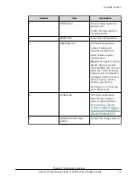
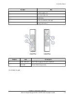


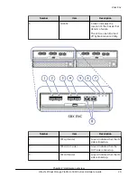
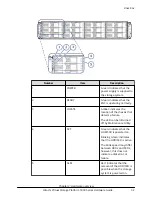

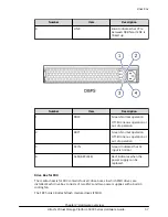
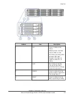

Number
Port 1
Port 2
Port 3
Port 4
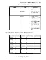
CHB-11E
2E
4E
6E
8E
CHB-11F
2G
4G
6G
8G
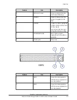
CHB-12A
2B
4B
6B
8B
CHB-12B
2D
4D
6D
8D
CHB-12E
2F
4F
6F
8F
CHB-12F
2H
4H
6H
8H
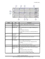
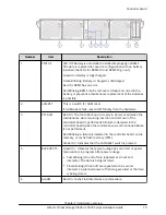
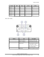
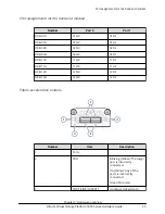
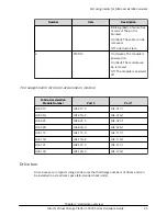
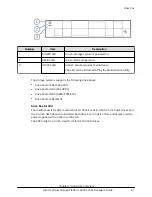
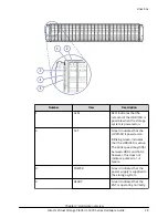
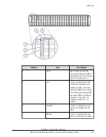
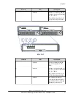
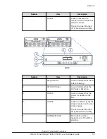
Back-end module
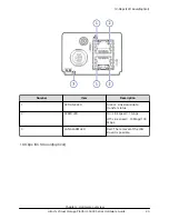
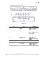
Number
Item
Description
1
PATH 0 connector
Connect to a drive tray.
2
PATH 1 connector
Connects to a drive tray.
3
STATUS LED
Green: Back end module is
in the power-on state.
Red: Back end module can
be removed safely.
4
PORT LED
Blue: Link status is normal.
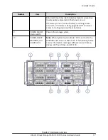
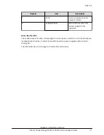
Back-end module
Chapter 2: Hardware overview
Hitachi Virtual Storage Platform 5000 Series Hardware Guide
24


