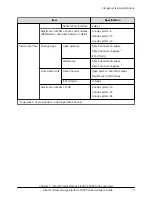


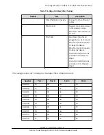
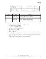

Number
Item
Description
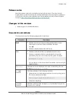
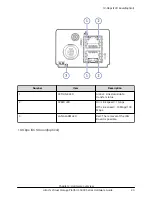
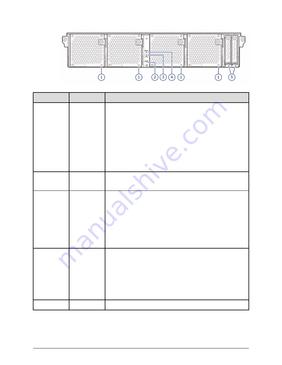
1
STATUS
LED Off: Battery is uninstalled, installed improperly or BKMF
firmware is replaced (in case of a configuration with no battery
installed, the LEDs for BKMF-10 and BKMF-20 go out).
Green On: Battery is fully charged.
Green Blinking: Battery is charged or discharged.
Red On: BKMF has an error.
Red Blinking: BKMF can be removed. A failure occurred in the
battery or preventive maintenance replacement of the batteries
is possible.
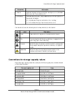
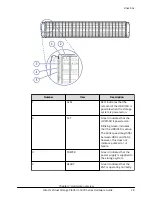
2
LAN-RST
This is a switch for GUM reset.
If GUM reboot fails, reset GUM forcibly from the hardware.
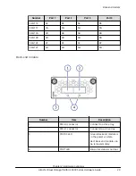
3
CTL ALM
Red On: The controller board is ready to be removed (when the
maintenance work requiring insertion and removal of the
controller board is performed). A failure is detected in the
controller board (when the maintenance work mentioned above
is not performed).
Red Blinking: A failure is detected in the controller board, cache
memory, or cache flash memory (CFM).
Amber On: Indicates that the LAN RESET switch is pressed.
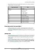
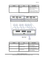
4
BACKUP STS
Green On : Indicates that power outage has occurred or power
restoration is in progress after power outage.
■
Fast blinking (On and off are repeated at 0.1-second
intervals.): The data is being restored.
■
Slow blinking (On and off are repeated at 0.5-second
intervals.): A planned power off is being executed or the data
is being stored.
5
ALARM
Red On: Cache Flash Memories are removable.
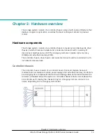
Controller board
Chapter 2: Hardware overview
Hitachi Virtual Storage Platform 5000 Series Hardware Guide
19