35
37PD5
2
00 (EU) (PW1)
Item COLOR
TEMPERATURE
ADJUSTMENT
-VIDEO
Applicable Model
37PD5
2
00
Preparation Procedure
[Adjustment of Cool mode]
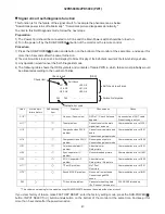
(1) Connect the AVC jig and set CRT COLOR
ANALYZER at the center of the screen panel.
(1) Enter the service adjustment mode, and confirm
that No.0(R), 1(G) and 2(B) are all 255. If the some
data are not, set to 255.
(2) Set AVC jig to “Standard” of VIDEO mode, and
input the full-white raster signal to component
terminal.
Signal condition
480i component
Video level: 0.700Vp-p
Sync level: 0.300Vp-p
Setup level: 0V
(2) Adjust the color temperature by way that reduces
the one or two data in No.0, 1 or 2.
(Note: At least one of them should be 255 after
adjustment.)
<Specification>
Color Temperature (Cool) for Video
12000K x=0.268
0.005
y=0.283
0.005
(3) Set the display size to “Full”.
[Adjustment of Normal mode]
(This item must be done before the color
temperature adjustment for PC mode.)
(3) Enter the service adjustment mode, and confirm
that No.3(R), 4(G) and 5(B) are all 255. If the some
data are not, set to 255.
(4) Adjust the color temperature by way that reduces
the one or two data in No.3, 4 or 5.
(Note: At least one of them should be 255 after
adjustment.)
<Specification>
Color Temperature (Normal) for Video
9300K x=0.285
0.005
y=0.293
0.005
[Adjustment of Warm mode]
(5) Enter the service adjustment mode, and confirm
that No.6(R), 7(G) and 8(B) are all 255. If the some
data are not, set to 255.
(6) Adjust the color temperature by way that reduces
the one or two data in No.6, 7 or 8.
(Note: At least one of them should be 255 after
adjustment.)
<Specification>
Color Temperature (Warm) for Video
6500K x=0.314
0.005
y=0.327
0.005
Summary of Contents for 32PD5000
Page 26: ...26 55PMA550 55HDM71 PW1 00E ...
Page 31: ...31 55PMA550 55HDM71 PW1 00E ...
Page 49: ...32PD5000 42PD5000 49 ...
Page 50: ...37P D5 00 0 50 ...
Page 51: ...55PMA550 51 ...
Page 52: ...32PD5000 42PD5000 52 ...
Page 53: ...55PMA550 55HDM71 53 ...
Page 54: ...32PD5000 42PD5000 54 ...
Page 55: ...32PD5000 42PD5000 55 ...
Page 56: ...32PD5000 42PD5000 56 ...
Page 57: ...55PMA550 55HDM71 57 ...
Page 58: ...32PD5000 42PD5000 58 ...
Page 59: ...55PMA550 55HDM71 59 ...
Page 67: ...67 32PD5000 42PD5000 11 Block diagram ...
Page 68: ...68 55PMA550E Block diagram ...
Page 72: ...72 55PMA550 12 Connection diagram PW1 55V CONNECTION DIAGRAM ...
Page 77: ...77 32PD5000 42PD5000 42PD5000 ...
Page 79: ...79 55PMA550 Wiring diagram Wiring diagram 1 2 ...
Page 80: ...80 55PMA550 Wiring diagram 2 2 ...
Page 83: ...83 32PD5000 42PD5000 42PD5000 ...
Page 84: ...84 37PD5200 37PD5000 ...
Page 85: ...85 55PMA550 14 Disassembly diagram ...
Page 89: ...89 55PMA550 ...
Page 90: ......
Page 91: ...THE UPDATED PARTS LIST FOR THIS MODEL IS AVAILABLE ON ESTA ...
Page 92: ...HITACHI SM005 Power Supply Block Diagram 92 ...
Page 93: ...HITACHI SM005 Panel Connectors 93 ...
Page 94: ...HITACHI SM005 Power Supply Circuit Board ...
Page 95: ...HITACHI SM005 Power Supply Circuit 1 of 5 ...
Page 96: ...HITACHI SM005 Power Supply Circuit 2 of 5 ...
Page 97: ...HITACHI SM005 Power Supply Circuit 3 of 5 ...
Page 98: ...HITACHI SM005 Power Supply Circuit 4 of 5 ...


