20
32PD5000/42PD5000 (PW1)
2
5
32PD5000/42PD5000
/37PD5200
(PW1)
Item
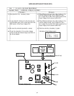
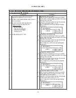
Vs and Va VOLTAGE ADJUSTMENT
Applicable Model
32PD5000, 37PD5000, 37PD5000
Preparation
Procedure
(1) Keep heat-run for 1 minutes or more.
(1) If the difference between the printed voltage of Vs
and the indicated value of Vs Voltmeter is over
0.1V, adjust the Vs ADJ VR located upward on the
Power Supply Unit to make it within 0.1V.
(2) Connect the DC Voltmeter to the Vs test point
and the GND point (or the Va test point and the
GND point) on the Power Supply Unit.
(2) If the difference between the printed voltage of Va
and the indicated value of Va Voltmeter is over
0.2V, adjust the Va ADJ VR located upward on the
Power Supply Unit to make it within 0.2V.
(3) Receive the all black signal with no setup.
(3) Check and do the procedure (1) again.
(4) Check the indication of Vs and Va voltages
printed on the label located upper right side on
the Panel Module.
<Example of the Voltage Label>
<LOT> **************
Vs= 80.0V
Va=60.0V
Vw=140.0V
Vx=60.0V
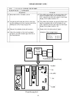
Power
Supply
Unit
X-sus
Y-sus
(Rear View)
Panel Module
Label
Vs ADJ
Va ADJ
Vs
GND
Va
MPF7409
S/N ********* *
MADE IN JAPAN
Power Supply Unit
Summary of Contents for 32PD5000
Page 26: ...26 55PMA550 55HDM71 PW1 00E ...
Page 31: ...31 55PMA550 55HDM71 PW1 00E ...
Page 49: ...32PD5000 42PD5000 49 ...
Page 50: ...37P D5 00 0 50 ...
Page 51: ...55PMA550 51 ...
Page 52: ...32PD5000 42PD5000 52 ...
Page 53: ...55PMA550 55HDM71 53 ...
Page 54: ...32PD5000 42PD5000 54 ...
Page 55: ...32PD5000 42PD5000 55 ...
Page 56: ...32PD5000 42PD5000 56 ...
Page 57: ...55PMA550 55HDM71 57 ...
Page 58: ...32PD5000 42PD5000 58 ...
Page 59: ...55PMA550 55HDM71 59 ...
Page 67: ...67 32PD5000 42PD5000 11 Block diagram ...
Page 68: ...68 55PMA550E Block diagram ...
Page 72: ...72 55PMA550 12 Connection diagram PW1 55V CONNECTION DIAGRAM ...
Page 77: ...77 32PD5000 42PD5000 42PD5000 ...
Page 79: ...79 55PMA550 Wiring diagram Wiring diagram 1 2 ...
Page 80: ...80 55PMA550 Wiring diagram 2 2 ...
Page 83: ...83 32PD5000 42PD5000 42PD5000 ...
Page 84: ...84 37PD5200 37PD5000 ...
Page 85: ...85 55PMA550 14 Disassembly diagram ...
Page 89: ...89 55PMA550 ...
Page 90: ......
Page 91: ...THE UPDATED PARTS LIST FOR THIS MODEL IS AVAILABLE ON ESTA ...
Page 92: ...HITACHI SM005 Power Supply Block Diagram 92 ...
Page 93: ...HITACHI SM005 Panel Connectors 93 ...
Page 94: ...HITACHI SM005 Power Supply Circuit Board ...
Page 95: ...HITACHI SM005 Power Supply Circuit 1 of 5 ...
Page 96: ...HITACHI SM005 Power Supply Circuit 2 of 5 ...
Page 97: ...HITACHI SM005 Power Supply Circuit 3 of 5 ...
Page 98: ...HITACHI SM005 Power Supply Circuit 4 of 5 ...


