background image

NOTE: This equipment has been tested and found to comply

with the limits for a Class B digital device, pursuant to Part 15 of

the FCC Rules. These limits are designed to provide reasonable

protection against harmful interference in a residential installation.

This equipment generates. uses and can radiate radio frequency

energy and, if not installed and used in accordance with the

instructions.

may

  h a r m f u l

interference to

radio

communications. However, there is no guarantee that interference

will not occur in a particular installation. If this equipment does

cause harmful interference to radio or television reception, which

can be determined by turning the equipment off and on, the user is
encouraged to try to correct the interference by one or more of the
following measures:

 Reorient or relocate the receiving antenna.
 Increase the separation between the equipment and receiver.
 Connect the equipment into an outlet on a circuit different from

that to which the receiver is connected.

 Consult the dealer or an experienced radio/TV technician for

help.

Warning:

A shielded-type power cord is required in order to meet FCC

emission limits and also to prevent interference to the nearby radio

and television reception.

It is essential that only the supplied

power cord be used.

Use only shielded cables to connect l/O devices to this

equipment.

You are cautioned that changes or modifications not

expressly approved by the party responsible for compliance could

void your authority to operate the equipment.

 VIII 

Summary of Contents for 17MVX-v2

Page 1: ...erences record the serial number of your display monitor SERIAL No The serial number is located on the rear of the monitor READ THE INSTRUCTION INSIDE CAREFULLY KEEP THIS USER MANUAL FOR FUTURE REFERENCES This monitor is Energy Star compliant when used with a computer equipped with VESA DPMS ...

Page 2: ......
Page 3: ...itted to the equipment is not suitable for your socket outlet it must be cut off and the appropriate plug fitted The cut off plug should be disposed of do not insert it into a 13 amp socket to prevent the hazard of electric shocks With plugs not incorporating a fuse the circuit must be protected by a 5 amp fuse WARNING THIS EQUIPMENT MUST BE EARTHED IMPORTANT Your equipment is supplied with a main...

Page 4: ...hich is marked with the letter L or coloured Red The wire which is coloured Blue must be connected to the terminal which is marked N or colourcd Black The plug moulded on to the cord incorporates a fuse For replacement use a 5 amp BS 1362 fuse Only ASTA approved fuses should be used The fuse cover carrier must be refitted when changing the fuse In the event of losing the fuse cover carrier the plu...

Page 5: ...e unit should never be enclosed or built upon unless adequate ventilation is provided 6 Do not remove the cover to try to service this unit Servicing of any nature should only be performed by authorized service personnel 7 WARNING Do not attempt to service this unit yourself as opening or removing covers may expose you to dangerous voltage or other hazards 8 The On Off switch is not a disconnectin...

Page 6: ...e power outlet This is a safety feature If you are unable to insert the plug into the outlet the outlet can be replaced by an electrician Do not defeat the safety purpose of the grounding type plug by improper use or alteration 12 Power source This monitor is able to operate using power sources from 108 264VAC 60 50Hz by means of internal auto power switching For 120V operation use only with power...

Page 7: ...es blockieren oder abdecken Diese frrungen und Schlitze im Gehause sorgen tir die notwendige Ventilation Das Bildschirmgerat sollte niemals mit einer Verkleidung umgeben oder in einem Regal eingebaut werden falls keine ausreichende Beltiftung vorhanden ist 6 Niemals versuchen das Gehause zu entfemen oder das Bildschirmgerat selber zu war ten Alle Wartungsarbeiten sollten nur vom Kundendienst durch...

Page 8: ...weise 11 Ihr Gerat ist mit einem dreipoligen Schukostecker ausgestattet Dieser Stecker kann nur an eine Schutzkontaktsteckdose angeschlossen wrerden Sollte der Stecker nicht in die Steckdose passen lassen Sie diese bitte von einem Elektriker auswechseln Es mu8 sichergestellt werden dal3 d i e minimale Bildwiederholfrequenz von 70 Hz bei Positivdarstellung und 60 Hz bei Negativdarstellung nicht unt...

Page 9: ...ancher Gerate zB Me sender kann allerdings gewissen Ems r ankungen unterliegen Beachten Sie deshalb die Hinweise in der Bedienungsanleitung Dem Bundesamt fur Zulassungen in der Telekommunikation wurde das inverkehrbringen dieses Gerates angezeigt und die Berechtigung zur ijberprtifung der Serie auf die Einhaltung der Bestimmungen eingeraumt VII ...

Page 10: ...ning the equipment off and on the user is encouraged to try to correct the interference by one or more of the following measures Reorient or relocate the receiving antenna Increase the separation between the equipment and receiver Connect the equipment into an outlet on a circuit different from that to which the receiver is connected Consult the dealer or an experienced radio TV technician for hel...

Page 11: ... OF CONTROLS 4 3 2 REWRITE COMPANY S NAME ON SCREEN 1 7 3 3 FUNCTIONS ADJUSTMENTS ON SCREEN 2 7 4 P O W E R M A N A G E M E N T S Y S T E M 10 5 PLUG PLAY 11 6 INSTALLATION _ 12 7 USE OF TILT SWIVEL 13 8 S P E C I F I C A T I O N ___ ____ ____ _ _ _____ __ 14 9 FACTORY PRESET DISPLAY MODES t 15 10 TROUBLE SHOOTING _ _ 15 I ...

Page 12: ... for PC and video standards including VGA SVGA XGA VESA and is even compatible with APPLE MAC II by using an inexpensive optional connector The 1280 X 1024 maximum resolution will help you get the most flexibility with today s or tomorrow s PC video standards Whether your video adapter has a multi frequency or fixed frequency analog colour signal it will interface with this colour monitor The unit...

Page 13: ...tallation please check the contents of the shipping carton The carton should contain the following items Power cord User manual Colour monitor If any of the above items are missing contact your supplier as soon as possible 3 ...

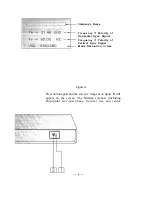
Page 14: ...range 2 POWER SWITCH Used to turn the power of the monitor ON and OFF 3 STATUS SELECT SWITCH Easy Menu Selects from screen 1 or screen 2 images and blanked windows for display Press button The screen 1 image as in figure A will be shown on the screen The company s name the polarity and frequencies of the horizontal and vertical sync signals and the resolution of the mode which is currently in use ...

Page 15: ...ync Signal Frequency Polarity of Vertical Sync Signal Mode Resolution in Use Figure A Press button again and the screen 2 image as in figure B will appear on the screen The tinction symbols including Horizontal size and phase Vertical size and center ...

Page 16: ...cription F ammeter Bar Figure B To clear the screen either push the status button again or wait for about 15 seconds The window will disappear automatically at that time 4 FUNCTION SWITCH Selects which function on screen 2 to be adjusted 5 ADJUST SWITCH Used to rewrite the company s name on screen 1 image and decrease or increase the parameter bar of the selected function on screen 2 image 6 SAVE ...

Page 17: ...er The new company s name may contain up to 10 characters Press function keys a or D as shown in item 4 on page 6 to select the character you wish to rewrite and then continuously press the adjust switch or f in order to select a letter or number The alphabet and numerals will be displayed in sequence Press SAVE key to save new company s name 3 3 FUNCTIONS ADJUSTMENTS ON SCREEN 2 For each fimction...

Page 18: ... CENTER c l El I E l pa PINCUSHION 0 n TRAPEZOID I CD CONTRAST CONTRAST CONTRAST INCREASED REDUCED a BRIGHTNESS e G R 2 COLOR lNTENSlN INTENSITY INCREASED REDUCED IMAGE ROTATION 01 o R CRT DEGAUSSING MANUAL DEGAUSSING cl WINDOW I I E l I c l RECALL RECALLS THE FACTORY PRESET MODES SEE PAGE 15 8 ...

Page 19: ...iew 1 AC socket Connect one end of the supplied power cord to this socket and the other end to the AC power outlet of the computer 2 Connect video cable with 15 pin male D SUB connector to the PC Video card 9 ...

Page 20: ...ches to saving mode screen darkens Note The power management system is initiated by the video signal sent from the PC side when the monitor is powered on If however the monitor is connected to a PC system that does not send out video signal a PC dead on arrival or a PC not powered on for example the user can still see the raster on the monitor screen like a traditional non power saving monitor The...

Page 21: ...pliant video card or PC By means of a software driver for a DDC video card or Windows 95 operation system all informations stored within the DDC device in the monitor such as resolution refresh rate and other data related to the monitor can be displayed for user s reference Based on this information users can for example select DDC2 only display mode with a different combination of resolution and ...

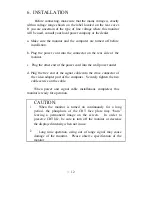
Page 22: ... the wall power outlet d Plug the free end of the signal cable into the drive connector of the video adapter port of the computer Securely tighten the two cable screws on the cable When power and signal cable installations completed this monitor is ready for operation CAUTION 1 When the monitor is turned on continuously for a long period the phosphors of the CRT face plate may bum leaving a perman...

Page 23: ...e tilt swivel base this unit can be adjusted to be viewed at the angle desired within 100 horizontally and 16 5 vertically Tilt Swivel Range To hands as turn the unit horizontally grasp it at its bottom illustrated below with both ...

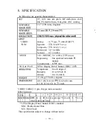
Page 24: ...Degaussing line operated automatic manual Consumption 115W max LUG PLAY VESA Display Data Channel DDC 1 2B IPERATING Temperature 0 to 40 degree C Humidity 10 to 90 R H Altitude 0 to 10 000 ft EIGHT 17 2 Kg 37 84 lb Approx IIMENSIONS 401 5 H X 410 4 W X 426 D mm 15 81 X 16 16 X 16 77 inch VIDEO CABLE 15 pin D type male connector DB 15 pin out 1234 5 6 7 8 9 10 11 12 13 14 15 RGBGndDDC R G B N C G n...

Page 25: ...dard VESA Standard VESA Standard 800x600 1 48 08 KHz 72 OHz i 1 I 1024 x 768 60 02 KHzl75 OHz 1024x768 48 36 KHz 6O OHz 1024 x 768 56 48 KHZ I 7O lHz 10 TROUBLE SHOOTING If there is no picture on the screen check the following 1 Is the monitor power on __ _ ___ If YES go to the next question I _ If NO turn the power on 2 Is your computer switch on tf Y Es x ion If NO turn the computer on 3 Is the ...

Reviews: