background image

- 9 -

Before Switching On Your TV

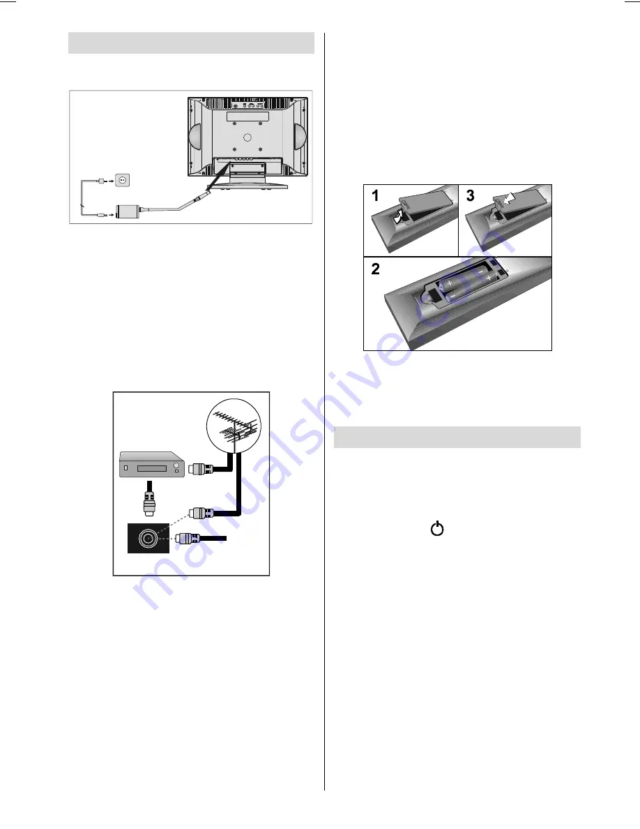
Power Connection

$&DGDSWHU

7R32:(5

,1387'&9

WHUPLQDO

IMPORTANT:

 The TV set is designed to op-

erate  on

 12 V DC. For this, an adaptor is

used which gives 12V DC voltage. Connect

this adaptor to a system that supplies 220-

240 V AC, 50 Hz.

• After unpacking, allow the TV set to reach the

ambient room temperature before you con-

nect the set to the mains.

Connections to the Aerial socket

9+)8+)

:

795($53$1(/

&$%/(79

6$7(//,7(5(&(,9(5

• Connect the aerial or cable TV plug to the

aerial socket located at the rear of the TV

and connect the cable plug coming out from

the TV out socket located on the devices

(VCR, DVB etc.) to this socket as well.

How To Connect Other Devices

IMPORTANT:

 Switch off the TV before con-

necting any external device.
Sockets  for  external  connections  are  at  the

rear side of the TV. For connection of other

devices via  SCART refer to the manuals of

the related devices.

Inserting Batteries In The Remote

Control Handset

• Remove the battery cover located on the

back of the handset by gently pulling up-

wards from the indicated part.

• Insert two AAA (R03) or equivalent type of

batteries inside.

• Replace the battery cover.

NOTE: 

Remove  the  batteries  from  remote

control handset when it is not to be used for

a long period.Otherwise it can be damaged

due to any leakage of batteries.

Switching The TV ON/OFF

To switch the TV on:

Your TV will switch on in two steps:

1-

 Connect the power supply cord to the sys-

tem. Press the “ ” (POWER) button at the

top of the TV. Then the TV switches itself to

stand-by mode and the led becomes red

located on the front of the TV.

2-

 To switch on the TV from stand-by mode

either:

Press a digit button on the remote control so

that a programme number is selected,
or,
Press “

-P/Ch

” or "

P/Ch+

”  button at the top of

the TV or press “

-P/CH

” or “

P/CH+

” button on

the remote control, so that last switched off

programme  is  selected.
Either way the TV will switch on and the LED

becomes  green.

(1*/,6+8.LQFK3L[HO:RUNV0%6$0:0S

Summary of Contents for 15LD2200

Page 1: ...GB Instructions for use 15LD2200 ...

Page 2: ...S 24 Tips 25 Care Of The Screen 25 Poor Picture 25 No Picture 25 Sound 25 Remote Control 25 Specifications 26 UK Guarantee 27 Important Instruction 28 Remote Control Buttons 2 Control Panel Buttons 3 Preparation 4 Installation of device on the wall 4 Features 6 Panel Features 6 Safety Precautions 6 Before Switching On Your TV 9 Power Connection 9 Connections to the Aerial socket 9 How To Connect O...

Page 3: ...gramme Up Volume Up TV Quit Menu External Source AV 1 RGB1 AV 2 SVHS PC Yellow button Blue button Hold Update Index Page Reveal PC Switch from TV to PC Expand Mix Teletext Time Subcode page Red button Green button Mute I II Mono Stereo Dual I II Volume Down P CH Programme Down Color temperature settings M Menu Cursor Down Cursor Left ...

Page 4: ... 3 ControlPanelButtons 227 723 29 5 92 80 0 18 3 K 32 5 0 18 92 80 3 K 63 5 1 5 5 5 9 5 ...

Page 5: ...ll where the monitor would be located Level and mark with a pencil the four 4 mounting points found on the wall bracket Drill pilot holes for the plastic anchors then secure the wall bracket with the four 4 L 32 mm x D 5 mm screws supplied Step 3 Raise the monitor with the mounting bracket attached and slip the top opening to the safety flange on the secured wall bracket Let the monitor fall in pl...

Page 6: ... 5 0 R X Q W LQ J E U D F N H W D OO E U D F N H W 3 O D V W L F D Q F K R U V P P P P V F U H Z V P P P P V F U H Z V P P P P V F U H Z V 6 7 5 8 7 8 5 0 2 1 7 2 5 ...

Page 7: ... sion lead or consult your dealer Observe the manufacturers instructions when connecting extension leads to the TV Check the fuse rating on the new plug this should be fitted with a 5 Amp fuse which conforms to either ASTA or BSI BS1 362 approvals these are easily identifiable by ei ther the or symbols If you are in Features Remote controlled colour television 100 programmes from VHF UHF bands or ...

Page 8: ...e case this could re sult in a fatal electric shock NEVER guess or take chances with electrical equipment of any kind it is bet ter to be safe than sorry 1 Power Source The TV set is designed to operate on 12 V DC The adaptor should be operated from a 220 240 V AC 50 Hz outlet Ensure you se lect the correct voltage setting for your conve nience 2 Power Cord The power supply cord should be placed s...

Page 9: ... manufacturer for the AC adaptor of the product 8 Servicing Please refer all servicing to qualified per sonnel Do not remove cover as this may re sult in electric shock 9 Naked Flame Sources Do not place naked flame sources on the apparatus WARNING When the device is not in use for a long time disconnect from power Instructions for waste disposal Packaging and packaging aids are recy clable and sh...

Page 10: ...o the manuals of the related devices Inserting Batteries In The Remote Control Handset Remove the battery cover located on the back of the handset by gently pulling up wards from the indicated part Insert two AAA R03 or equivalent type of batteries inside Replace the battery cover NOTE Remove the batteries from remote control handset when it is not to be used for a long period Otherwise it can be ...

Page 11: ...0 WR FDQFHO 2 WR VWDUW If you want to cancel A P S function press the M button If OK button is pressed A P S starts and the following warning is displayed 3 6 LV UXQQLQJ 3OHDVH DLW 0 WR H LW After A P S is finalized Program Table will be displayed on the screen In the Program Table you will see the programme numbers and names assigned to the programmes Operating with the buttons on the TV set Volu...

Page 12: ...a menu item and button to enter the menu item To exit a menu press the M button picture menu By pressing button select the first icon Picture menu appears on the screen GRZQ IRU SLFWXUH VHWWLQJV EULJKWQHVV FRQWUDVW VKDUSQHVV FRORXU SLFWXUH ILOWHU VKDUS brightness By pressing button select bright ness Press button to increase bright ness Press button to decrease bright ness Brightness level can be ...

Page 13: ...Frequency changes the horizontal width of picture to fix the picture on the screen By pressing button select fre quency Press button to increase fre quency Press button to decrease fre quency Frequency level can be adjusted be tween 0 and 100 audio menu By pressing button select the sec ond icon Audio menu appears on the screen GRZQ IRU DXGLR VHWWLQJV YROXPH EDODQFH H WHQGHG DXGLR IHDWXUHV DXGLR 9...

Page 14: ...er menu appears on the screen GRZQ IRU HTXDOL HU VHWWLQJV HTXDOL HU GE GE GE Press button to select the first frequency band Press button to select the other frequency bands Selected band can be adjusted by pressing button Press button on the first band to exit the equalizer menu headphone menu By pressing button select the third icon Headphone menu appears on the screen GRZQ IRU KHDGSKRQH VHWWLQJ...

Page 15: ... button to slide screen up Press button to slide screen down v position can be adjusted between 0 and 100 options menu By pressing button select the fourth icon Options menu appears on the screen GRZQ IRU RSWLRQ VHWWLQJV PHQX EDFNJURXQG ODQJXDJH VOHHS WLPHU RSWLRQV URRP OLJKWLQJ RSDTXH QJOLVK EULJKW FKLOG ORFN RQ RII menu background By pressing button select menu background You can change menu bac...

Page 16: ...select installa tion and press button Installation menu appears on the screen programming GRZQ WR SURJUDPPLQJ RSWLRQV SURJUDP QXPEHU SURJUDP QDPH VWDQGDUG VWRUH SURJUDPPLQJ PDQXDO VHDUFK RQ RII IUHTXHQF 0K SURJU VNLS ILQH WXQLQJ 872 program number By pressing button select pro gram number Press button to select the first or the second digit Then press digit buttons on remote control to enter the p...

Page 17: ... sec ond icon Program table appears on the screen GRZQ WR DGMXVW FKDQQHO RUGHU SURJUDP WDEOH 79 Program table shows the programme num bers and the names assigned to the programmes Here you can adjust the channel order by moving or deleting the channels First of all press the button Using the GREEN button you can move a programme into another programme s loca tion Press the direction buttons to sel...

Page 18: ...H 5 3 6 29 520 1 1 50 1 1 6 6 6 7 1 63 1 785 6 32578 8 6 87 DVW HVW ULOOLF HVW DVW HVW UHHN teletext region By pressing button in the Settings menu select teletext region There are two options to select West and East OtherFeatures TV Status Programme Number Programme Name and Sound Indicator are displayed on screen after programme change for 3 sec onds 3 Programme Number 35 Programme Name 5 charac...

Page 19: ...B1 mode is supported from AV1 In order to quit the AV mode press the the digit buttons or the P CH or P CH PC Mode Press PC button to switch directly to PC mode Press P CH P CH or digit buttons to quit the PC mode Teletext Teletext is an information system that dis plays text on your TV screen Using the Tele text information system you can view a page of information on a subject that is available ...

Page 20: ...the button to stop the automatic page change Press the button again to allow the next page to be displayed To Select A Subcode Page Subcode pages are subsections of long Teletext pages that can only be displayed on the screen one section at a time Select the required Teletext page Press the button Select the required subcode page number by pressing four digit buttons e g 0001 If the selected subco...

Page 21: ...al is RGB1 select RGB1 by pressing the button Via Aerial Input If you want to connect to your TV peripherals like video recorders or decoders but the de vice you want to connect does not have Scart you should connect it to the Aerial in put of the TV If the VCR is connected via aerial input it is suggested that you use Programme 0 Decoder Cable TV offers you a wide choice of pro grams Most of them...

Page 22: ... 21 9 6 9 2 1387 9 2 1387 8 2 1387 5 8 2 1387 9 3 1387 1 287 1 287 5 3 21 6 57 62 7 9 5 PeripheralEquipmentConnections ...

Page 23: ...ctPeripheralEquipment 17 1 1 36 6 8 2 1 5 9 2 1 1 287 1 2 8 7 HULDO DECODER FOR SATELLITE RECEIVER VIDEO HEADPHONE AUDIO AerialConnections 9 8 9 HULDO 5RXQG RKP FRD LDO FDEOH 5HDU RI 79 2XWGRRU HULDO RQQHFWLRQV ...

Page 24: ...r to AV 2 input at the rear side of the TV Connect your equipment to the TV via VIDEO yellow AUDIO R red and AUDIO L white inputs You must connect the jacks to the in put using the same color To Connect To S VHS Input Connect your camera or camcorder S VHS input at the rear side of the TV Connect your equipment to the TV via S VHS input and audio inputs of AV 2 inputs by us ing S VHS cables Connec...

Page 25: ... Hz and a horizontal sync frequency range of 30 57 KHz The following table is an illustration of some of the typical video display modes RUL RQWDO 9HUWLFDO RU N 9HU 0RGH UHTXHQF 5HVROXWLRQ The native resolution of the TFT LCD Panel is 1024 x 768 Therefore using Mode 6 is ad vised to get the best PC input display quality ...

Page 26: ...htly to the aerial socket Is the aerial cable damaged Are suitable plugs used to connect the aerial If you are in doubt consult your dealer No Picture means that your TV is not receiv ing any transmission Have you pressed the correct buttons on the remote control Try once more Sound You can not hear any sound Did you per haps interrupt the sound pressing the button Are external speakers connected ...

Page 27: ...ESETCHANNELS 100 CHANNEL INDICATOR On Screen Display RFAERIALINPUT 75 Ohm unbalanced OPERATINGVOLTAGE 220 240 V AC 50 Hz AUDIO Nicam Stereo AUDIO OUTPUT POWER WRMS 10 THD 2 x 3 POWER CONSUMPTION W max 38 W 3 W Stand by PANEL 4 3 display 15 Screen Size Dimensions WxHxD W 462 mm H 355 mm with stand D 170 mm with stand 76 mm without stand Weight 5 6 Kg ...

Page 28: ...r modified by any person other than an Hitachi authorised engineer iii The product serial number has not been removed or altered This guarantee does not apply to product acquired second hand or for commercial or com munal use This guarantee does not cover the replacement of exhausted batteries the adjustment of user controls or aerial alignment Any parts replaced under this guarantee shall become ...

Page 29: ...hich is marked with the letter E or by the earth symbol or coloured green or green and yellow The wire which is coloured blue or black must be connected to the terminal which is marked with the letter N or coloured Black The wire which is coloured brown or red must be connected to the terminal which is marked with the letter L or coloured Red For continued protection against risk of fire replace o...

Page 30: ...Benelux Branche Office Bergensesteenweg 421 1600 Sint Pieters Leeuw BELGIUM TEL 0032 2 363 99 01 FAX 0032 2 363 99 00 Email consumer mail hitachi eu com HSE DUS Service Hitachi eu com customerservice italy hitachi eu com france consommateur hitachi eu com info hitachi be HITACHI EUROPE S A GREECE HITACHI EUROPE S A SPAIN HITACHI EUROPE AB SWEDEN HITACHI EUROPE LTD NORWAY 364 Kifissias Ave 1 Delfon...

Reviews: