background image

MAINTENANCE AND ADJUSTMENT OF THE UTV                         


- 97 -

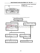
Coolant temperature warning light checking method 


Turn the main switch “ON”. 

Coolant  temperature  warning  light 

does not come on. 

Coolant  temperature  warning  light 

come on. 

Turn  the  main  switch  to  “START” 

with  the  transmission  in  neutral 

position.   

Coolant  temperature  warning  light 

comes on momentarily . 

Coolant  temperature  warning 

light does not come on. 

Coolant  temperature  and  electrical 

circuit are OK .Go ahead with riding. 

Check the electrical circuit 


CHECKING THE COOLANT TEMPERATURE 

WARNING LIGHT 

Coolant temperature indicator light 


Summary of Contents for HS450UTV

Page 1: ...e read the handbook through and fully understand it otherwise any improper repairing and amounting would bring you problems and accident may occur in your use Proper use and maintenance can guarantee...

Page 2: ...ly 4 Cleaning parts 5 Warning labels 5 SERIAL NUMBERS 6 FASTENERS 6 Torque specifications 6 Self locking fasteners 6 Washers 6 Cotter pins 7 Snap rings and E clips 7 SHOP SUPPLIES 8 Lubricants and Flu...

Page 3: ...eler gauge 17 Calipers 17 Micrometers 18 Adjustment 18 Care 19 Metric micrometer 19 Standard inch micrometer 20 Telescoping and small bore gauges 21 Dial Indicator 21 Compression gauge 22 Multimeter 2...

Page 4: ...engine 33 ENGINE WILL NOT START 34 Identifying the problem 34 Spark test 35 The starter cannot work repeatedly or can only work slowly 36 POOR ENGINE PERFORMANCE 36 The engine starts slowly or difficu...

Page 5: ...HIGH OIL CONSUMPTION OR EXCESSIVE 44 Exhaust smoke 44 Low oil pressure 44 High oil pressure 44 No oil pressure 44 Oil level too low 44 Oil contamination 45 CYLINDER LEAK DOWN TEST 45 ELECTRICAL TESTI...

Page 6: ...iper 55 Leaking master cylinder 55 CHAPTER 2 SPECIFICATIONS HOW TO USE CONVERSION TABLE OF UNIT 57 How to use conversion table 57 Definition of unit 57 GEBERAR SPECIFICATIONS 58 ENGINE SPECIFICATIONS...

Page 7: ...rk arrester 99 Adjusting the brake pedal 99 Adjusting the parking brake 100 Checking the brake fluid level 101 Checking the front brake pads 101 Checking the rear brake pads 102 Checking the brake hos...

Page 8: ...TE 124 ENGINE REMOVAL 125 CYLINDER HEAD AND CYLINDER HEAD COVER 128 ROCKER ARMS VALES AND CAMSHAFT 131 VALVES AND VALVE SPRINGS 135 CYLINDER AND PISTON 140 ENGING COOLING FAN AND A C MAGNETO 144 BALAN...

Page 9: ...Side cover Footrest part 193 Cargo rack 197 Cargo bed 200 Head shed frame 204 DIRECTION SYSTEM Steering wheel part 206 Steering mechanism part 209 BRAKE SYSTEM 214 Disk brake components 215 WHEEL AND...

Page 10: ...S 283 Checking the switch 285 Checking the switch continuity 286 Checking the bulbs and bulb sockets 287 IGNITION SYSTEM 287 Circuit diagram 287 Troubleshooting 288 ELECTRIC STARTING SYSTEM 291 Circui...

Page 11: ...3 Typical components of EMS 313 Layout of EMS components 314 COMPONENTS OF EMS Electronic control unit 314 Multec 3 5 injectors 315 Throttle body assembly with stepper motor 319 Engine coolant tempera...

Page 12: ...AULTY GEAR SHIFTING 336 Shift lever does not move 336 Jumps out of gear 336 ENGING OVERHEATING 337 Overheating 337 FAULTY BRAKE 337 Poor braking effect 337 SHOCK ABSORBER MALFUNCTION 338 Loss of dampi...

Page 13: ...he first time WARNINGS CAUTIONS AND NOTES The terms WARNING CAUTION and NOTE have specific meaning in this manual WARNING emphasizes areas where injury or even death could result from negligence Mecha...

Page 14: ...Cap 13 Passenger Safety Belt 14 Passenger Seat 15 Gearshift Arm Assy 16 Passenger Handrail 17 Front Tire 18 Cooling Water Tank Component 19 Welding Assembly Front Bumper 20 Horn Switch 21 Light Switc...

Page 15: ...GENERAL INFORMATION 3 IDENTIFICATION CODE Frame No Frame No is carved on the right side of front main frame Engine No Engine NO Is carved on the right side of the engine Figure...

Page 16: ...illing grinding hammering compressed air and chemicals 11 Wear the correct clothing for the job Tie up or cover long hair so it does not get caught in moving equipment 12 Do not carry sharp tools in c...

Page 17: ...the home garage Many types of chemical cleaners and solvents are available for shop use Most are poisonous and extremely flammable To prevent chemical exposure vapor buildup fire and serious injury o...

Page 18: ...various subassemblies are not installed and tightened correctly Fasteners that are improperly installed or work loose can cause extensive damage it is essential to use an accurate torque wrench as des...

Page 19: ...ecure parts within housing bores In some applications in addition to securing the component s snap rings of varying thicknesses also determine endplay These are usually called selective snap rings The...

Page 20: ...il satisfies The classifications are MA high friction applications and MB low frication applications NOTE Refer to Engine Oil and Filter in Chapter Three for further information on API SAE classificat...

Page 21: ...most common from of antifreeze Check the UTV Manufacturer s recommendations when selecting antifreeze Most require one specifically designed for aluminum engines There types of antifreeze have additiv...

Page 22: ...carried out with basic hand tools and test equipment familiar to the home mechanic Always use the correct tools for the job Keep tools organized and clean Store them in a tool chest with related tools...

Page 23: ...und on the driving faces or flutes of the screwdriver s tip figure 4 ACR Phillips II screwdrivers were designed as part of a manufacturing drive system to be used with ACR Phillips II screws but they...

Page 24: ...ntact the fastener at only two points which makes them more subject to slipping off the fastener Because one jaw is adjustable and may become loose this shortcoming is aggravated Make certain the soli...

Page 25: ...le to remove stubborn fasteners without damaging them Impact drivers and interchangeable bits Figure 10 are available from most tool suppliers When using a socket with an impact driver Make sure the s...

Page 26: ...ause of the size of the torque wrench head drive and socket If a torque adapter changes the effective lever length Figure 14 the torque reading on the wrench will not equal the actual torque applied t...

Page 27: ...are needed to cut wire and can be used to remove cotter pins Use needle nose pliers to hold or bend small objects Locking pliers Figure 16 sometimes called Vise Grips are used to hold objects very tig...

Page 28: ...TOOLS The ability to accurately measure components is essential to perform many of the procedures described in this manual Equipment is manufactured to close tolerances and obtaining consistently accu...

Page 29: ...quid crystal display LCD to show the measurement Properly maintain the measuring surfaces of the caliper There must not be any dirt or burrs between the tool and the object being measured Never force...

Page 30: ...just care for and read the measurements of various types of outside micrometers For accurate results properly maintain the measuring surfaces of the micrometer There cannot be any dirt or burrs betwee...

Page 31: ...ure the spindle and anvil faces do not contact each other or another object If they do temperature changes and corrosion may damage the contact faces 3 Do not clean a micrometer with compressed air Di...

Page 32: ...025 in increments Every fourth sleeve mark is numbered 1 2 3 4 5 6 7 8 9 These numbers indicate 0 100 0 200 0 300 and so on The tapered end of the thimble has 25 lines marked around it Each mark equa...

Page 33: ...ore Do not over tighten the gauge because there is no built in release Excessive tightening can damage the bore surface and damage the tool Remove the gauge and measure the outside dimension Figure 30...

Page 34: ...f using a meter not recommended by the manufacturer Such requirements are noted when applicable Ohmmeter analog calibration Each time an analog ohmmeter is used or if the scale is changed the ohmmeter...

Page 35: ...current to operate in a battery powered system Resistance Resistance is the opposition to the flow of electricity within a circuit or component and is measured in ohms Resistance causes a reduction in...

Page 36: ...s off painted surfaces 6 Use penetrating oil on frozen or tight bolts Avoid using heat where possible Heat can warp melt or affect the temper of parts Heat also damages the finish of paint and plastic...

Page 37: ...l out during assembly Do not apply grease to electrical or brake components Removing Frozen Fasteners If a fastener cannot be removed several methods may be used to loosen it First apply a penetrating...

Page 38: ...igure 40 is available from most tool suppliers This tool makes the removal and installation of studs easier If one is not available thread two must onto the stud and tighten them against each other Re...

Page 39: ...ions as a guideline NOTE Unless otherwise specified install bearings with the manufacturer s mark or number facing outward Removal While bearing are normally removed only when damaged there may be tim...

Page 40: ...aft and into the housing at the same time a tight fit is required for both outer and inner bearing races In this situation install a spacer underneath the driver tool so that pressure is applied evenl...

Page 41: ...le and evaporate immediately the temperature is correct Heat only one housing at a time CAUTION Do not heat the housing with a propane or acetylene torch Never bring a flame into contact with the bear...

Page 42: ...Storage Area Selection When selecting a storage area consider the following 1 The storage area must be dry A heated area is best but not necessary It should be insulated to minimize extreme temperatu...

Page 43: ...e intake and exhaust openings 2 Service the air filter as described in Chapter Three 3 Inspect the cooling system Check the drain plug and hose connections for leaks 4 Refill the fuel tank Turn the fu...

Page 44: ...k at the right time If one basic requirement is missing the engine will not run STARTING THE ENGINE When experiencing engine starting troubles it is easy to work out of sequence and forget basic start...

Page 45: ...he volume of oil when in idle speed automatically Countermeasure When start the engine run 2 to 3 minutes in idle speed If it can t run normally in idle turn off the engine and restart it repeatedly 1...

Page 46: ...ient amount of fuel to start the engine 4 If there is sufficient fuel in the fuel tank remove the spark plug immediately after attempting to start the engine The plug s insulator should be wet indicat...

Page 47: ...CAUTION After removing the direct ignition coil or spark plug cap and before removing the spark plug in Step 1 clean the area around the spark plug with compressed air Dirt that falls into the cylind...

Page 48: ...stment 3 The fuel tank connection hose is clogged 4 The fuel hose is clogged or the oil filter is clogged 5 The injector is clogged NOTE If a warm or hot engine will start with the choke on or if a co...

Page 49: ...e following 1 Lean throttle pilot system 2 Loose exhaust pipe to cylinder head connection 3 Faulty ignition system component 4 Check the following engine components a Broken valve springs b Stuck or l...

Page 50: ...ase Check for one or more of the following problems a Clogged air filter b Restricted fuel flow c Pinched fuel tank breather hose Figure 9 d Clogged or damaged silencer or muffler NOTE A clogged exhau...

Page 51: ...rrect Perform the Peak Voltage 2 Check the fuel system as described in this chapter 3 Check the valve clearance as described Note the following a If the valve clearance as correct Perform Step 4 b If...

Page 52: ...n can result c If there is too much fuel on the end of the spark plug go to check whether there is overflow at the air filter or the ducting damper Rich Mixture The following conditions can cause a ri...

Page 53: ...mixes with the oil in the crankcase sludge is produced Sludge can eventually cause engine damage as it circulates through the lubrication system and blocks off oil passages Large amounts of steam can...

Page 54: ...amber 6 Dragging brake s 7 Slipping clutch The Ignition Advance Angle Is Too Large Preignition is the premature burning of fuel and is caused by hot spots in the combustion chamber Glowing deposits in...

Page 55: ...ion chamber 2 Slapping or rattling noises at low speed or during acceleration May be caused by excessive piston to cylinder wall clearance piston slap NOTE Piston slap is easier to detect when the eng...

Page 56: ...High Oil Pressure 1 The lubrication oil pressure valve is stuck and closed 2 Clogged oil filter 3 Clogged oil gallery or metering orifices No Oil Pressure 1 Low oil level 2 The lubrication oil pressu...

Page 57: ...e it will be necessary to lock the engine at TDC on its compression stroke and then perform the leak down test Follow the manufacturer s directions along with the follow the manufacturer s directions...

Page 58: ...nd and shift the transmission into top gear with the shift pedal b Mount a holding tool or equivalent onto the drive sprocket Use a wooden block and clamp to hold the holding tool so it cannot move wh...

Page 59: ...ound or switch If the other circuits work properly and the shared wiring is good the cause must be in the wiring used only by the suspect circuit If all related circuits are faulty at the same time th...

Page 60: ...an open circuit Other heat related problem occur when a component creates its own heat as it starts to fail or go bad a Troubleshoot the problem to help isolate the problem or area b To check a conne...

Page 61: ...y given circuit The voltmeter unlike the test light also indicates how much voltage is present at each test point When using a voltmeter attach the positive lead to the component or wire to be checked...

Page 62: ...per wire is a simple way to bypass a potential problem and isolate it to a particular point in a circuit If a faulty circuit works properly with a jumper wire installed an open exists between the two...

Page 63: ...ote the voltage reading The reading should be within I volt of battery voltage If the voltage is less There is a problem in the circuit Voltage drop test The wires Cables Connectors and switches in an...

Page 64: ...res or components within the circuit A circuit with an open On the other hand has no continuity This type of test can be performed with a self powered test light or an ohmmeter An ohmmeter gives the b...

Page 65: ...ely When replacing or refilling the brake fluid use only DOT 4 brake fluid from a closed container Always check the brake operation before riding the motorcycle Soft or Spongy Brake Lever or Pedal Ope...

Page 66: ...Brake caliper not sliding correctly on slide pins 15 Sticking master cylinder piston assembly 16 Sticking brake caliper pistons Brake Drag When the brakes drag the brake pads are not capable of moving...

Page 67: ...rped brake disc 5 Loose brake disc mounting bolts 6 Brake caliper not sliding correctly on slide pins 7 Mismatched brake pads 8 Damaged wheel bearings Brake Squeal or Chatter 1 Contaminated brake pads...

Page 68: ...GENERAL INFORMATION 56 4 Loose banjo bolt washers 5 Damaged banjo bolt washers 6 Damaged banjo bolt threads in master cylinder body 7 Loose or damaged reservoir cap...

Page 69: ...0 6214 3 281 1 094 0 3937 0 03937 mph mi ft yd in in Volume capacity cc cm3 cc cm3 lit liter lit liter 0 03527 0 06102 0 8799 0 2199 oz IMP liq cu in qt IMP liq gal IMP liq Others kg mm kg cm2 Centig...

Page 70: ...ore stroke Compression ratio Starting system Lubrication system HS183MZ Liquid cooled 4 stroke SOHC Forward inclined single cylinder 454cm3 83 84mm 3 27 3 31in 9 4 1 Electric starter Wet sump Engine o...

Page 71: ...8 Chassis Frame type Trail Toe in Steel tube frame 26 0mm 1 02 in 8 18 mm 0 31 0 71 in Tire Type Size Front Rear Pressure of front wheel Pressure of rear wheel Tubeless 25 8 12 min 27 9 14 max 25 10 1...

Page 72: ...ttage quantity Headlight Front Position Lamp Front direction indicator Rear direction indicator Rear position lamp Brake Lamp Neutral Reverse Coolant temperature Parking brake Four wheel drive Differe...

Page 73: ...Cylinder Bore size Measuring point 91 000 91 015mm 3 582 3 583 in 50 mm 1 97 in Camshaft Drive method Cam dimensions Intake A B Exhaust A B Camshaft runout limit Chain drive Left 32 30 32 20 mm 1 271...

Page 74: ...diameter face width seat width margin thickness A head diameter IN EX B face width IN EX C seat width IN EX D margin thickness IN EX Stem outside diameter IN EX Guide inside diameter IN EX 39 9 40 1...

Page 75: ...ner spring Free length Outside spring IN EX Within spring IN EX Set length valve closed Outside spring IN EX Within spring IN EX Compressed pressure installed Outside spring IN EX Within spring IN EX...

Page 76: ...in 4 0mm 0 15in 0 5mm 0 0394in Intake side 20 002 20 008mm 0 7875 0 7877in 19 99 19 995mm 0 7870 0 7872 in 0 15 mm 0 0059 in Piston rings Top ring Type Dimensions B T End gap installed Side clearance...

Page 77: ...0276 in 0 06 0 15 mm 0 0024 0 0059 in Crankshaft Crank width A Runout limit C1 C2 Big end side clearance D Big end radial clearance E 74 95 75 00 mm 2 9508 2 9528 in 0 35 0 65 mm 0 0138 0 0256 in 0 01...

Page 78: ...00 r min Cylinder head 0 23 mm 0 0091 in 0 17 mm 0 0067 in 0 24 mm 0 0094 in Water pump Type Reduction ratio Single suction centrifugal pump 32 31 1 032 Shaft drive Middle gear backlash Final gear bac...

Page 79: ...9 15N mm 3 99 kg mm 62 5N mm 6 37 kg mm 30 88 mm 1 18 3 46in 88 140mm 3 46 5 51 in Front wheel Type Rim size Rim material Rim runout limit radial lateral Aluminum Alloy wheel 12 6 AT min 14 7 AT max A...

Page 80: ...e diameter Brake fluid type Dual 200 3 5 mm 7 87 0 14 in 6 0 mm 0 24 in 6 0 mm 0 24 in 19 0mm 0 75in 25 0mm 1 57in DOT 4 Rear disc brake Type Disc outside diameter thickness Pad thickness inner Pad th...

Page 81: ...e 25325359 Charging system Nominal output Charging coil resistance color 14 V 25 A at 4 500 r min 0 32 0 43 at 20 68 F White White White Rectifier regulator Regulator type No load regulated voltage DC...

Page 82: ...it Electric starter system Type Starter motor Output Armature coil resistance Brush overall length Starter relay Amperage rating Coil winding resistance Constant mesh type 0 8 kW 0 025 0 035 12 5 mm 0...

Page 83: ...Oil pump assembly Oil cooler inlet pipe 1 oil cooler outlet pipe 1 Oil cooler inlet pipe 1 oil cooler outlet pipe 1 clamp Oil cooler inlet pipe 2 oil cooler outlet pipe 2 clamp Intake manifold Intake...

Page 84: ...10 1 0 7 2 Starter clutch Bolt M8 3 30 3 0 22 Clutch carrier assembly Nut M22 1 160 16 0 115 Stake Clutch housing assembly Bolt M6 9 10 1 0 7 2 Bearing retainer middle drive shaft Screw M8 4 29 2 9 2...

Page 85: ...ator bracket and frame Bolt M6 4 7 0 7 5 1 Fuel pump Bolt M6 2 7 0 7 5 1 Fuel tank Bolt M8 2 30 3 0 22 Muffler stay Bolt M6 2 11 1 1 8 0 Muffler and exhaust pipe Bolt M8 1 20 2 0 14 Muffler bracket an...

Page 86: ...13 1 3 9 4 Differential gear case cover and differential gear case M8 25 2 5 18 Rear driving axle gear case and frame M10 70 7 0 51 Rear driving axle gear case filler plug M20 23 2 3 17 Rear driving a...

Page 87: ...nd constant velocity joint of half shaft M20 260 26 0 190 Stake Rear brake hose and frame M6 7 0 7 5 1 Brake pipe and brake master cylinder M10 19 1 9 13 Pedal holder assembly and frame M8 16 1 6 11 B...

Page 88: ...hten multi fastener assemblies in a crisscross pattern and progressive stages until the specified tightening torque is reached Unless otherwise specified tightening torque specifications require clean...

Page 89: ...tridge O ring Apply lithium soap based grease Starter idle gear shaft Apply molybdenum disulfide grease Starter wheel gear Apply engine oil Clutch housing assembly shaft end Apply lithium soap based g...

Page 90: ...nt of front brake cable Light lithium base grease Front brake lever axle and rear brake lever axle Light lithium base grease Adjusting nut and pin of front brake cable Light lithium base grease Adjust...

Page 91: ...SPECIFICATIONS 79 HYDROGRAPHIC CHART Hydrographic chart Pressure splash...

Page 92: ...SPECIFICATIONS 80 LUBRICATION OIL WAY LUBRICATION OIL WAY Pressure splashing oil...

Page 93: ...filter element clean Replace if necessary Every20 40hours More often in wet of dusty areas Front brake Check operation fluid leakage Correct if necessary Rear brake Check operation Adjust if necessar...

Page 94: ...Engine oil filter cartridge Replace Final gear oil Check oil level oil leakage Replace Differential gear oil Lights and switches Check operation Adjust headlight beams NOTE Recommended brake fluid DOT...

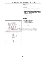
Page 95: ...rance must be adjusted when the engine is cool to the touch Adjust the valve clearance when the piston is at the Top Dead Center TDC on the compression stroke Remove lift the cargo bed up driver seat...

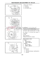
Page 96: ...According to the rotor turning counterclockwise rotor turn to mark the dead spots of crank box namely the dead point position is compressed 4 Check valve clearance Beyond the standard Adjust Valve cle...

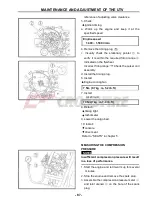
Page 97: ...clearance rules with the valve clearance If the gap beyond the standard value repeat the above steps until the correct gap 6 Install all removed parts According to remove the reverse order for install...

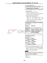
Page 98: ...spark plug with a spark plug cleaner or wire brush 6 Install spark plug 18 Nm 20 Nm 1 8 m kg 13 ft lb Then hook up the spark plug cap NOTE Before installing a spark plug clean the gasket surface and...

Page 99: ...he pulser coil assembly d Install the timing plug 6 Install Engine cooling fan 7 Nm 0 7 kg m 5 2 lb ft 7 Install Air shroud 10 Nm 1kg m 7 4 lb ft 8 Detach timing light tachometer 9 Lower the cargo bed...

Page 100: ...able below Compression pressure with oil introduced into cylinder Reading Diagnosis Higher than without oil Worn or damaged pistons Same as without oil Defective ring s valves cylinder head gasket or...

Page 101: ...pstick in when checking the oil level Recommended oil Follow the left chart NOTE Recommended oil classification API Service SE SF SG type or equivalent e g SF SE CC SF SE SD etc NOTE Do not allow fore...

Page 102: ...oil filter cartridge is also to be replaced perform the following procedure Remove the oil filter cartridge with an oil filter wrench Lubricate the O ring of the new oil filter cartridge with a thin c...

Page 103: ...NGINE in chapter 4 11 Check engine oil pressure a Slightly loosen the oil gallery bolt b Start the engine and keep it idling until engine oil starts to seep from the oil gallery bolt If no engine oil...

Page 104: ...the engine with the air filter element removed This will allow unfiltered air to enter causing rapid wear and possible engine damage Additionally operation without the filter element will affect carbu...

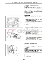
Page 105: ...hat the sealing surface of the element matches the sealing surface of the case console driver seat lower the cargo bed CHECKING THE COOLANT LEVEL 1 Place the vehicle on a level surface 2 Remove front...

Page 106: ...r 3 Connect coolant reservoir hose 4 Remove coolant drain bolt water pump along with the copper washer 5 Remove radiator cap WARNING A hot radiator is under pressure Therefore do not remove the radiat...

Page 107: ...l cooling with the specified amount of the recommended coolant Recommended antifreeze High quality ethylene glycol antifreeze containing corrosion inhibitors for aluminum engines Mixing ratio 1 1 anti...

Page 108: ...types of antifreeze NOTE Adding water instead of coolant lowers the antifreeze content of the coolant If water is used instead of coolant check and if necessary correct the antifreeze concentration of...

Page 109: ...e warning light come on Turn the main switch to START with the transmission in neutral position Coolant temperature warning light comes on momentarily Coolant temperature warning light does not come o...

Page 110: ...imit 29 9 mm 1 18 in Replace V belt Install the bolts into the secondary fixed sheave hold NOTE Tightening the bolts will push the secondary sliding sheave away causing the gap between the secondary f...

Page 111: ...the engine when removing the tailpipe from the muffler 3 Remove Remove the bolts Remove the tailpipe by pulling it out of the muffler 4 Install Insert the tailpipe into the muffler and align the bolt...

Page 112: ...STING THE PARKING BRAKE 1 Shift the drive select lever into neutral gear 2 Remove lift the hood up Refer to SEATS in chapter5 3 Check parking brake cable free play Out of specification Adjust Parking...

Reviews: