background image

Installation Instructions

UM19.5A User Manual, 99159, March 2017 

 13

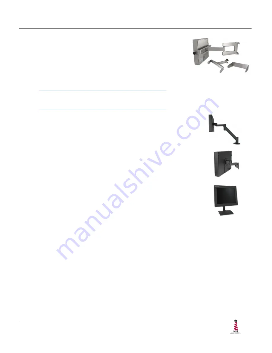
Heavy Industrial Arm Mounts

Our wall arm mounting options range from solid wall yoke to fully 

articulating arms.  Complete installation instructions are shipped with 

the following products and may also be found on our website at the 

following addresses:

Wall Mount Arms (for YA _ _ -15 and YA _ _ -24 Series):

http://www�HopeIndustrial�com/Installations/99090�pdf

Wall Yoke (for YW _ _ -07 Series):

http://www�HopeIndustrial�com/Installations/99091�pdf

VESA Radial Arm

The VESA Radial Arm Mount is designed to suspend our Universal Mount 

Monitors above a working area.

VESA Wall Mount Bracket

The VESA Wall Mount Bracket allows simple, effective mounting of our 

Universal Mount Monitors to any vertical surface.

VESA Benchtop Stand

The VESA Benchtop Stand allows easy, stable positioning of our Universal 

Mount Monitors on any flat surface.

Summary of Contents for HIS-UM19.5-***A

Page 1: ...USER MANUAL Model No HIS UM19 5 _ _ _ A REVISION A 19 5 UNIVERSAL MOUNT INDUSTRIAL MONITOR ...

Page 2: ...stations 11 Install Cable Exit Cover Plate 11 Mount the Monitor 12 Video Settings 15 Setting the Timing Mode 15 Control Panel Buttons 16 OSD and Power Lock Settings 17 On Screen Display OSD Menus 18 Auto Image Adjust Menu 19 Contrast Brightness Menu 19 Input Select Menu 19 Audio Adjust Menu 19 Color Adjust Menu 20 Information Menu 21 Manual Image Adjust Menu 21 Setup Menu 22 Memory Recall Menu 23 ...

Page 3: ...o be powered by a Listed Power Supply suitable for the application with outputs at SELV LPS or Class 2 levels rated 9 6 36 6VDC 2 5 A max The equipment is not intended to connect directly to a DC Mains source FCC Notice This equipment has been tested and found to comply with the limits for a Class A digital device pursuant to Part 15 of the FCC Rules These limits are designed to provide reasonable...

Page 4: ...nt is suitable for use in Class I Division 2 Groups A B C and D Class II Division 2 Groups F and G Class III or non hazardous locations only WARNING EXPLOSION HAZARD Do not disconnect equipment unless power has been removed or the area is known to be non hazardous WARNING EXPLOSION HAZARD Substitution of any components may impair suitability for Class I II III Division 2 Locations NOTE Hope Indust...

Page 5: ...awings UM19 5A User Manual 99159 March 2017 5 Mechanical Drawings Front View Rear View 437 4 mm 17 22 317 5 mm 12 50 241 3 mm 9 50 514 4 mm 20 25 CABLE ENTRY 98 8 mm 3 89 514 4 mm 20 25 317 5 mm 12 50 241 3 mm 9 50 ...

Page 6: ...ings 6 UM19 5A User Manual 99159 March 2017 Side View 158 8 mm 6 25 34 3 mm 1 35 Side Mounting Holes 1 4 20 Internal Thread x 0 625 Deep 71 2 mm 2 80 KEYBOARD optional 174 0 mm 6 85 123 7 mm 4 87 KVM EXTENDER optional ...

Page 7: ...at the air temperature around the unit top and bottom will not exceed the rated specifications of the unit f f The maximum rated temperature for the HIS UM19 5 is 50 C 122 F f f Remember that even though this product is designed to operate at 50 C the life span of any electronic device is shortened when it is consistently operated at high temperatures Therefore it is wise to take steps to keep the...

Page 8: ...llowing instructions to connect power video and touch screen if applicable to your monitor Video Connection The HIS UM19 5 supports digital video through its DVI port and analog video through its VGA port After selecting the appropriate interface connect one end of your video cable to the input port on the rear of the monitor and the other end to the appropriate port on your host computer or other...

Page 9: ...and drivers for all major operating systems To be sure that you have the most current information please check the following Internet address http www HopeIndustrial com Touchscreen_Drivers htm IMPORTANT If you will be using a USB connection install the touch screen driver first and then connect the USB cable If you will be using a Serial connection connect the Serial cable first and then install ...

Page 10: ...e adequate strain relief 2 Select the appropriate driver for your operating system a If downloading from the web address listed above select the appropriate driver for your operating system b If using the included CD insert it into the host computer s CD ROM drive If the CD does not automatically run browse the contents of the CD and open the READ ME FIRST htm file in a web browser Select the appr...

Page 11: ...ion should you need to disassemble or reassemble it for any reason They may also be found on our website at the following address http www HopeIndustrial com Installations 99108 pdf Install Cable Exit Cover Plate Installation instructions vary slightly depending on the Cable Exit Cover Plate you ordered Complete installation instructions are shipped with each Cover Plate configuration and may also...

Page 12: ...rdware http www HopeIndustrial com Installations 99025 pdf YB N12 KIT for YB _ _ BLK N12 Series http www HopeIndustrial com Installations 99026 pdf Yoke and Benchtop Mounting Kit for YB Series http www HopeIndustrial com Installations 99027 pdf Heavy Industrial Pedestal Mounts Our Yoke and Pedestal Mount allows full range of pan and tilt motion while our Fixed Pedestal Mount provides a sturdy solu...

Page 13: ..._ 15 and YA _ _ 24 Series http www HopeIndustrial com Installations 99090 pdf Wall Yoke for YW _ _ 07 Series http www HopeIndustrial com Installations 99091 pdf VESA Radial Arm The VESA Radial Arm Mount is designed to suspend our Universal Mount Monitors above a working area VESA Wall Mount Bracket The VESA Wall Mount Bracket allows simple effective mounting of our Universal Mount Monitors to any ...

Page 14: ...llation instructions for specific VESA mounting options are shipped with the product and may also be found on our website at the following address http www HopeIndustrial com Installations 99034 pdf If using VESA mounting screws not supplied by Hope Industrial Systems ensure they do not intrude into the enclosure more than 12 7 mm 0 5 IMPORTANT UNIVERSAL MOUNT MONITOR NYLON WASHERS RUBBER WASHERS ...

Page 15: ...een image TIP For the best picture quality set your computer graphics adapter timing mode to VESA 1920 x 1080 60 Hz Please refer to the computer graphics adapter manufacturer s manual for instructions on setting the resolution and timing mode In Microsoft Windows these settings may be found at the following location f f 2000 XP Control Panel Display Settings f f Vista Control Panel Personalization...

Page 16: ...us and adjustment screens disappear automatically after 15 seconds This is adjustable through the OSD Time Out setting in the Setup menu 2 To select a control to adjust press the up or down button to scroll through the menu 3 Press button 2 to open the menu for a selected control 4 To adjust the control press the up or down button 5 To save the adjustments and return to the main OSD menu press but...

Page 17: ...ems in the menu down Enter When the OSD menu IS NOT displayed Shortcut to Auto Image Adjust When the OSD menu IS displayed Displays the control screen for the highlighted control OSD and Power Lock Settings f f OSD Lock Press and hold 1 and the up button for 10 seconds If any buttons are pressed the message OSD Locked will display for 3 seconds f f OSD Unlock Press and hold 1 and the up button aga...

Page 18: ... between inputs Audio Adjust HIS UM19 5 monitors do not include audio capabilities these functions are inoperative for Hope Industrial monitors Color Adjust Provides several color adjustment modes Information Displays the timing mode video signal input Manual Image Adjust Includes the H V Position Horizontal Size Fine Tune Sharpness Aspect Ratio ECO Mode View Mode and Blue Light Filter functions S...

Page 19: ... is more than one computer connected to the display Use D Sub for analog VGA signals and DVI for digital signals Auto Image Adjust Menu The Auto Image Adjust menu automatically sizes centers and fine tunes the video signal to eliminate waviness and distortion Press button 2 outside of the OSD menu to activate Auto Image Adjust NOTE Auto Image Adjust works with most common video cards If this funct...

Page 20: ...en image for cooler white used in most office settings with fluorescent lighting Native Adds red to the screen image for warmer white and richer red Warm Adds red to the screen image for warmer white and richer red User Color Individual adjustments for red R green G and blue B 1 To select color R G or B press button 2 2 To adjust selected color press the up or down button NOTE If you select RECALL...

Page 21: ...h rate is 60 Hz Manual Image Adjust Description H V Position Moves the screen image left or right and up or down Horizontal Size Adjusts the width of the screen image Fine Tune Sharpens the focus by aligning text and or graphics with pixel boundaries NOTE Try the Auto Image Adjust function first Sharpness Adjusts the clarity and focus of the screen image Aspect Ratio Selects the image size for 4 3...

Page 22: ...r different applications as well as the default Standard setting This feature may also be accessed by pressing the up button outside of the OSD menu Game adjusts the gamma curve to enhance darker scenes and improve visibility in brighter scenes Movie adjusts the contrast to enhances the black levels Web adjusts the gamma curve to improve contrast and color Text adjusts the color temperature contra...

Page 23: ... For example with a 15 second time setting if a control is not pushed within 15 seconds the display screen disappears OSD Background Allows the user to turn the OSD background On or Off Auto Power Off When enabled this setting will automatically power off the monitor when no signal is detected for 3 minutes Power Indicator Allows the user to turn the Power Indicator light On or Off Memory Recall M...

Page 24: ...CLOTH PREFERABLY MADE OF COTTON All displays may be cleaned using any standard glass cleaner as long as there is no abrasive or oily content Vinegar or ammonia will not hurt the screen The anti reflective coatings on glass window equipped displays are physically part of the surface of the glass and resist degradation to the Military Specifications To minimize over run of cleaning solution spray th...

Page 25: ...cator light is lit blue Check power connections at the monitor and power source For DC models check the connector polarity and ensure input voltage is 9 6 to 36 6 VDC The Auto Power Off function is enabled Disable this setting by unchecking the box for the Auto Power Off function in the OSD s Setup menu No image on the screen and control s Power Indicator light is lit orange Video cable is not plu...

Page 26: ...ctly for the source signal Activate the Auto Image Adjust function in the OSD menu Fine tune the picture by manually adjusting the image In the OSD menu these functions can be found in the Manual Image Adjust menu Wrong or abnormal colors white is not white Monitor color settings are incorrectly adjusted Reset the monitor to the factory default settings by activating the Memory Recall function in ...

Page 27: ...es the USB cable length exceed 5 meters USB cables have a 5 meter limitation and could cause no touch response if this is exceeded If using a Serial connection is the Serial cable plugged into the correct COM port Ensure that the Serial cable is connected to the COM port being used prior to installing the touch screen driver The cursor moves but does not follow my finger when touching the touch sc...

Page 28: ...Ratio typical 3000 1 static Backlight typical LED 40 000 hour brightness half life Environmental Operating Temperature 0 to 50 C 32 to 122 F Storage Temperature 20 to 60 C 4 to 140 F Humidity 20 to 90 non condensing Operating Shock 15 g 6 msec half sine Operating Vibration sine 1 0g swept sine 9 500 Hz Transport Vibration random 0 1g2 Hz 10 200 Hz 0 03g2 Hz 200 2000 Hz Altitude Operating up to 10 ...

Page 29: ...5 Hz Supported Video Standards 1920 x 1080 60 Hz 1680 x 1050 60 Hz 1600 x 1200 60 Hz 1400 x 1050 60 Hz 1440 x 900 60 75 Hz 1280 x 1024 60 75 Hz 1280 x 960 60 Hz 1280 x 720 60 Hz 1152 x 870 75 Hz 1024 x 768 60 70 75 Hz 832 x 624 75 Hz 800 x 600 56 60 72 75 Hz 720 x 400 70 Hz 640 x 480 60 67 72 75 Hz Response Rate typical 20 ms Functional Control Panel Buttons Power 1 Menu Up Down 2 Enter On Screen ...

Page 30: ... model 8 62 kg 19 lbs Shipping Weight Black Powder Coated Carbon Steel model 8 62 kg 19 lbs Stainless Steel model 10 43 kg 23 lbs Compliances and Certifications Electrical UL 60950 3rd Edition cUL Listed Product File No E212889 FCC Class A CAN ICES 3A NMB 3A CE Environmental IEC 60721 3 Reliability WEEE Registration No WEE DJ1859ZX for UK only Enclosure UL 50E File No E212889 Hazardous Location Fo...

Page 31: ...ed we will give you a Return Material Authorization RMA number This RMA number must be conspicuously marked on the outside of the shipping box Hope Industrial Systems will not accept shipments not accompanied by the RMA number Except where otherwise noted you must ship or deliver the product to Hope Industrial Systems Freight prepaid What Does This Warranty Not Cover This warranty does not cover e...

Page 32: ...les and Customer Service sales HopeIndustrial com Support and Returns support HopeIndustrial com Accounting Department accounting HopeIndustrial com www HopeIndustrial com UK Harling Road Snetterton Norwich NR16 2JU United Kingdom Phone 44 0 20 7193 2618 Fax 44 0 20 7117 1194 Sales and Customer Service sales HopeIndustrial co uk Support and Returns support HopeIndustrial co uk Accounting Departmen...

Reviews: