background image

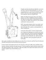
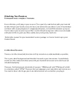
If you use a PWM-based receiver, it’s pretty straightforward. Look at the wires coming from 

the receiver and match them with the plugs on the left side of your Control Board. “AIL” will 

go to the “AIL” plug, “ELE” will go to the “ELE” plug, “THR” to “THR,” and “RUDD” to “RUDD.” 

(Side note: Those stand for “aileron,” “elevator,” “throttle,” and “rudder.”)

With a PWM-based receiver, for those four channels you’ll plug the AIL servo into the AIL 

channel, the RUDD to the RUDD channel, the ELE to ELE, and the THR to THR. 

On your receiver, there will be a fifth channel that’s used for the self-leveling mode. This 

could be called “AUX,” “Gear,” “Channel 5,” or some other name, depending on your 

receiver’s manufacturer. You need to refer to your receiver’s manual to know what it’s 

named. This allows you to switch between manual-leveling mode and self-leveling mode 

using a switch on your transmitter. There are other methods of doing this switching, but 

we highly recommend you do your switching through your transmitter by plugging in your 

“AUX” to the AUX channel.

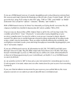
If you use a PPM-based receiver, all information for AIL, ELE, THR, RUDD, and AUX come 

through one servo cable. Plug the PPM output wire from the receiver into the “AIL” plug. 

Keep in mind, though, if you use a PPM receiver you will have to make a final adjustment 

in the end of the programming of your Control Board, as the KK 2.1 is set for PWM-based 

receivers by default.

As we said, this section is NOT to be used as your instructions for connecting your receiver. 

Don’t rely upon it. Instead, make sure to use the instructions for your receiver for connecting 

it properly.

If you can’t find installation instructions for your receiver, you can find links to the most 

popular receivers on our website at www.GameofDrones.com/diymanuals.

Summary of Contents for Game of Drones

Page 1: ......

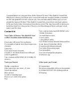
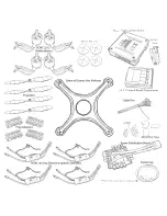
Page 2: ...owing One Game of Drones Hiro airframe Five lengths of plastic trim four longer one shorter Cable ties Four wood motor mounts One KK 2 1 HC Multi Rotor Control Board with Programmer Two clockwise CW R...

Page 3: ......

Page 4: ...u re building The side without the hole is the bottom shell The bottom shell is symmetrical so you don t need to worry about a front or back Now take your components out of the box and verify you have...

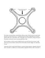
Page 5: ...use a small piece of tape and a pen to number your arms so you can easily find them later Pull out the box of two motors with black cap screws the box of two motors with green cap screws the four wood...

Page 6: ...h the top of the frame This step is a bit fiddly and can be challenging the first time you do it but once you get the hang the other three will go on fairly quickly NOTE DO NOT USE LOCTITE OR ANY SCRE...

Page 7: ...can t swivel the motor a bit to get the other three holes to line up Then screw in the other three screws Once you ve got all four screws in place go back and tighten all four screws firmly but not t...

Page 8: ...ors go on Arm 1 and Arm 3 and your CW motors go on Arm 2 and Arm 4 Now string all the wires coming out of the motors through the little slot in the frame next to the motor It s easiest to string these...

Page 9: ...o make your Power Distribution Board as flat as possible so split the red and black wires apart and orient the wires so the black wire is to the left of the plugs closest to where it attaches to the b...

Page 10: ...on Board over so the black squishy side is up and lay it over your KK 2 1 Control Board sandwiching the power cables between the two boards The power cables and the yellow tip should be pointing away...

Page 11: ...r other components Do this for all four ESCs It doesn t matter which set of black and red plugs you use but you ll want to space them out a bit We recommend plugging one ESC into the right side of the...

Page 12: ...plug on your Power Distribution Board to give you more or less slack Why is this important Because the computer chip important to navigation is located right below where the arrow is on the case Putt...

Page 13: ...e the squishy side of the Distribution Board Control Board then stick it to your frame in the posi tion you just tested out Attaching the Servos Estimated time to complete 5 minutes Now you re ready t...

Page 14: ...Now do the same with ESC 2 the one that will go in Arm 2 plugging it into to position 2 on your Control Board Follow up with ESC 3 and ESC 4 into positions 3 and 4...

Page 15: ...e You need to know which type your transmitter receiver set uses before you plug in Attaching Your Receiver Estimated time to complete 15 minutes Now is the time you ll plug in your receiver This is p...

Page 16: ...en manual leveling mode and self leveling mode using a switch on your transmitter There are other methods of doing this switching but we highly recommend you do your switching through your transmitter...

Page 17: ...made any mistakes and everything is spinning properly First go through all your connections and make sure you ve done them correctly especially the power cables between your ESCs and your Power Distr...

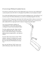
Page 18: ...are using a PPM based receiver If you are using a PWM based receiver skip this section The KK 2 1 is set by default to use PWM so no extra steps are needed First check and double check your connectio...

Page 19: ...t your Programmer to the ribbon cable and plug in the battery to the power cable The screen on your programmer will display that you are in safe mode Press the rightmost menu button and using the Down...

Page 20: ...Turn on your transmitter and plug in your battery You ll hear a few beeps and the Control Board and your receiver will power up Now let s make sure your Control Board is getting signal from your trans...

Page 21: ...ly sure that your surface really is level Do it on a flat table or a floor Once you hit continue the accelerometer will calibrate itself Just make sure that once you ve started the calibration you do...

Page 22: ...your Programmer While you hold the keys down have your friend attach the battery Keep holding them down The screen on your Programmer will read Throttle Pass Through and you will hear a series of bee...

Page 23: ...aren t touching the motors so it impedes their spin Plug in your battery and tuck it inside your drone Place it on a flat floor or a table with nothing around it that could get caught in the motors T...

Page 24: ...the adapters on the flat over the shaft of the motor By trial and error find the adapter that fits snuggly over the shaft but not so tight you have to force it Keep trying larger and smaller adapters...

Page 25: ...rease the throttle until it lifts off the ground and hovers If if does you re ready to close it up for good If it doesn t check your propeller rotations and make sure you have the right propellers on...

Page 26: ...ost taste it huh Well then let s get this finished up Remove the zipties you used to temporarily close your drone Then pull out the clear plastic gaskets and slide the four long gaskets over the flang...

Page 27: ...hen you re using them This damages the batteries and increases the danger Regularly inspect your LiPo batteries If you ever find one of your LiPos is damaged or if one is puffed up like a little ballo...

Page 28: ...xperienced trainers The Academy of Model Aeronautics endorses a number of schools that can get you flying right You can find a list of RC instructionprograms at www modelaircraft org under Education W...

Page 29: ...Build It Yourself kit and more important thank you for building it We hope you enjoy flying it and we re always looking for your feedback Visit www GameofDrones com for more information and to sign u...

Page 30: ...2015 Game of Drones Ballistic UAV Inc...

Reviews: