background image


Part No. 4801-1015 Rev 6-09 


Super-Saver XL Heater – 120 Volt 

Page


16


of 

25


b


Gate


valve


Arbitrary Piping System


d


f


Heaters 

Heaters 

30


m


m


Gas meter


8


m


tees


10.  Pipe Sizing Guidelines 

10.1  Calculating HVR & ELOP 

1. 

Using a system schematic, label each piping 
section of the system starting at the meter or 
regulator.  A different pipe section starts 
where the gas demand of the system 
changes, usually at a junction. 

2. 

Determine the Heating Value Required 
(HVR) in BTUH (BTU's per hour) for each 
section of pipe. 

HVR = (no. heaters supplied by pipe 
section) X (heat output per heater)


3. 

Determine the Equivalent Length Of Pipe (ELOP) 
required for sufficient gas service. 

ELOP = (length from meter to most remote heater) 
+ (Minor loss equivalents of the system)


IMPORTANT:  Use the ELOP value from this 
equation for size determination of all pipe sections. 

4. 

Use the ELOP value from step 3, and the HVR of 
each pipe section to determine the required pipe size 
for either natural gas (NG) (Table 1) or liquid propane 
(LP) (Table 2) from the table 'Maximum Capacity Of 
Pipe'.


10.2  Directions for Reading Pipe Size from Tables: 

EXAMPLE:  Four 40,000 BTUH (12 kW) heaters will be installed on the gas pipe line in the 'Arbitrary Piping System' 
diagram below.  NOTE:  Values given in English and Metric equivalent units. 

1.  Determine the HVR value for each pipe section of the system.


Pipe Section 

No. Of Heaters 

HVR Calculation 

HVR Value  


BTUH 

kW 

BTUH 

kW 

a-b 

4 x 40,000 

4 x 12 

160,000 

48 

b-c 

2 x 40,000 

2 x 12 

80,000 

24 

c-e 

1 x 40,000 

1 x 12 

40,000 

12 

b-d 

1 x 40,000 

1 x 12 

40,000 

12 

b-f 

1 x 40,000 

1 x 12 

40,000 

12 

c-g 

1 x 40,000 

1 x 12 

40,000 

12 

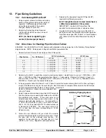
2.  Determine the ELOP.  Length from meter to most remote heater = length from a to e (or g) = 100ft (30m) + 25ft 

(8 m) = 125ft (38 m)  Minor loss equivalents from Table 1 = 1 gate valve x  2ft/valve (1 m/valve) + 3 tees x 11 
ft/tee (4 m/tee) =35ft (13 m).  Calculated ELOP = 125ft (38 m) + 35ft (13 m) = 160 ft (51 m)  Tabulated ELOP = 
200ft (60 m)  Round up to the nearest table value. 

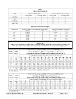
3.  In the appropriate table, NG (Table 2) or LP (Table 3), select the column showing the ELOP or the next longer 

length, if the table does not give the exact length.  Use this column to compare table values to the HVR values.  
Use the Natural Gas table (Table 2) in this example.  From step 2,  
ELOP = 200ft (60 m)  Locate the column labeled 200ft 
(60 m) in Table 2. 

4. 

Select a pipe section and read down the ELOP column to 
find the maximum gas capacity that matches the HVR for 
that particular pipe section.  If the exact value is not 
listed, choose the next larger value in the column.  In this 
example, start with pipe section c-e.  For pipe section c-
e, HVR = 40,000 BTUH (12 kW). From Table 2, column 
200 ft,  40 (12) is not listed (NOTE: The table values are 
in thousands of BTUH's).  The next larger value of 72 
(21) is read from the table, corresponding to 72,000 
BTUH (21 kW). 

5.  Follow the row leftward until you reach the columns 

labeled 'Internal Diameter' and 'Nominal pipe size'.  Read 
the pipe size for the particular pipe section.  For 
example, for pipe section c-e, the pipe size is ¾ inch 
(0.824 in.) (19.1 mm).  Repeat for each pipe section. 

Summary of Contents for HH-SS-120-XL

Page 1: ...e de gaz FOR YOUR SAFETY Do not store or use gasoline or any flammable vapors and liquids in the vicinity of this or any other appliance CONSIGNES DE SECURITE II es interdit d utiliser des liquides inflammables ou degageant des vapeurs inflammables a proximite de tout appareil fonctionnant au gaz Agricultural Building Heater 120 Volt Retain Instructions for Future Reference MODEL BTUH kW HH SS 225...

Page 2: ...fire or explosion property damage personal injury or loss of life WARNING Not for home or recreational vehicle use Installation of this heater in a home or recreational vehicle may result in a fire or explosion property damage personal injury or loss of life WARNING Proper gas supply pressure must be provided to the inlet of the appliance Refer to rating plate for proper gas supply pressure Gas pr...

Page 3: ... Pipe Glue 1 4 7 mm Nut Driver Install screw hooks with hammer or drill Model No Maximum Input Ventilation air required to support combustion SS 40 XL 40 000 BTUH 11 7 kW 500 CFM 849 5 m3 hr SS 75 XL 75 000 BTUH 21 9 kW 500 CFM 849 5 m3 hr HH SS 120 XL 120 000 BTUH 35 2 kW 1000 CFM 1699 m3 hr HH SS 175 XL 175 000 BTUH 36 6 kW 1000 CFM 1699 m3 hr HH SS 200 XL 200 000 BTUH 58 6 kW 1000 CFM 1699 m3 h...

Page 4: ... living quarters 10 Not to be used for heating where flammable liquids and vapors are stored or used 11 Inadequate gas volume and or pressure will directly influence the combustion efficiency of the heater Adequate gas volume and or pressure is the responsibility of the installer 12 Adequate ventilation is required 13 Combustion and ventilation air must not be obstructed 14 Not for use with duct w...

Page 5: ... clean B Burner orifice and hot surface ignition assembly must be kept clean and free of carbon build up C Check blower wheel regularly for dust accumulation and clean periodically for maximum airflow D Thermostat coils must be kept clean to assure proper temperature control E Igniter must be cool before wash down Do not operate heater for one hour following wash down WARRANTY Your Super Saver XL ...

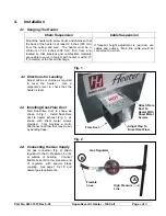
Page 6: ...irections for Leveling Adjust cables or chains as required to level the heater Use a carpenter s level to check that the heater is level 4 3 Installing Dual Flare Duct Fold Dual Flare duct to shape as shown in Fig 1 Install Dual Flare duct to heater exhaust Fig 1 as shown with sheet metal screws provided This provides a multi directional heat flow that may be set by bending flaps 4 4 Connecting th...

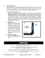
Page 7: ...e heater will operate every time power is supplied and the on off switch is activated If an external thermostat is to be used See Component Wiring Diagram the heater will operate only when power is supplied the on off switch is activated and the thermostat indicates a call for heat 5 2 Starting Up Adjust thermostat higher than house temperature Allow 20 seconds for heater to ignite On initial star...

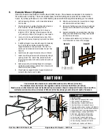
Page 8: ...h sheet metal screws provided 9 Place heater on support bracket Support bracket must be level before heater is set in place 10 Slide thru wall extension duct assembly into flange and secure with sheet metal screws 11 Place outer flashing seal around thru wall extension duct and secure with sheet metal screws to inside of wall 12 Fasten directional duct to extension duct mounting flange then bend d...

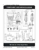
Page 9: ...CTRONIC MODULE Transformer STATUS INDICATOR 1 4 5 2 3 7 6 8 GREEN BLACK WHITE YELLOW YELLOW IND L1 HSI HSIG L2 W PSI FSI GV PSO FSG C BLUE BLACK ORANGE BROWN WHITE YELLOW GRAY YELLOW RED YELLOW GREEN Option 1 Piggy Back Thermostat COMPONENT AND WIRING DIAGRAM 120 Volts A C 60 Hz Single Phase FSI FSI 1 2 IPON CONNECTORS INSIDE HEATER INSIDE HEATER INSIDE HEATER Option 2 Low Voltage Control Direct W...

Page 10: ...HERMOSTAT 10 AMP FUSE ON OFF TRANSFORMER 24 VAC 40VA 60 Hz MOT FLAME SENSOR PROBE GND REDUNDANT VALVE MAIN VALVE HIGH LIMIT SWITCH SAIL SWITCH IND LI HSI HSIG L2 PSO FSG PSI W GV C LINE VOLTAGE LOW LINE WHITE BLACK UNITED TECHNOLOGIES Hot Surface Ignition Control FSI LADDER TYPE SCHEMATIC DIAGRAM 120 Volts A C 60 Hz Single Phase IGNITOR ...

Page 11: ... listed below will help determine if system is operating properly The igniter will warm up and glow bright red The main burner flame will ignite The main burner flame will continue to burn after the igniter is turned off Trouble shooting the system consists of checking for these three visual indications The Visual Check Charts define the proper action if any of these indications do not occur DANGE...

Page 12: ...nt 4 Status Indicator Flashing Four Times When the status indicator LED shows the repeating error code of four flashes the control has gone into lock out due to a failure within the control board 9 3 Checking Manifold Pressure To be performed by a certified gas technician only 1 Unplug heater from power source and turn ball valve to OFF position 2 Remove outlet pressure tap plug from gas control v...

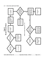
Page 13: ...Part No 4801 1015 Rev 6 09 Super Saver XL Heater 120 Volt Page 13 of 25 9 4 Chart 1 First Visual Check Chart 1 First Visual Check ...

Page 14: ...Part No 4801 1015 Rev 6 09 Super Saver XL Heater 120 Volt Page 14 of 25 9 5 Chart 2 Second Visual Check Chart 2 Second Visual Check NOTE All voltage readings 10 15 ...

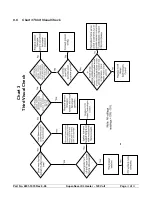
Page 15: ...Part No 4801 1015 Rev 6 09 Super Saver XL Heater 120 Volt Page 15 of 25 9 6 Chart 3 Third Visual Check Chart 3 Third Visual Check ...

Page 16: ...000 4 x 12 160 000 48 b c 2 2 x 40 000 2 x 12 80 000 24 c e 1 1 x 40 000 1 x 12 40 000 12 b d 1 1 x 40 000 1 x 12 40 000 12 b f 1 1 x 40 000 1 x 12 40 000 12 c g 1 1 x 40 000 1 x 12 40 000 12 2 Determine the ELOP Length from meter to most remote heater length from a to e or g 100ft 30m 25ft 8 m 125ft 38 m Minor loss equivalents from Table 1 1 gate valve x 2ft valve 1 m valve 3 tees x 11 ft tee 4 m...

Page 17: ...3000 15800 12800 10900 9700 8800 8100 7500 7200 6700 5500 4600 3783 3432 Table values given in BTUH 1000 To convert to kW multiply table values by 0 3 1 inch 25 4 mm Pipe Sizes Determined For Diagram Pipe Section Max Gas Capacity Value Determined From Table 2 Pipe Size Determined From Table 2 BTUH kWh inches mm a b 280 000 82 1 1 4 in 31 8 b c 135 000 40 1 in 25 4 b d 72 000 21 in 19 1 b f 72 000 ...

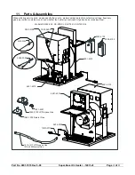
Page 18: ... type inside or outside mount and whether the heater is constructed of galvanized or stainless steel 1045 1305 Natural Gas 1045 0100 LP Propane Gas 1021 2501 6401 4501 3005 0108 1903 3800 6401 4515 6401 4512 0404 2358 6450 0094 3002 3004 3005 2130 3005 0102 1010 1317 LP Propane Gas 1010 2500 Natural Gas 6401 4510 Models SS 225 XXL SS 200 XL SS 175 XL SS 1290 XL 11 Parts Assemblies ...

Page 19: ...1496 1041 1491 1021 1495 3004 0100 LP Propane Gas 3004 0101 Natural Gas 1041 5004 SEE MODEL NO 1004 1422 1004 1102 Models HH SS 225 XL HH SS 200 XL HH SS 175 XL HH SS 120 XL 6401 1308 1004 1102 0404 7036 0404 6674 0404 1140 OSM 0404 3000 1004 1406 0404 6703 OSM 6401 4513 ISM 6401 4504 ISM 6401 1151 6401 1140 ...

Page 20: ... XL and HH SS 120 XL 6401 1318 1004 0107 6401 4508 1001 1452 0408 6673 1004 1388 1004 1410 1004 1130 0408 5017 1001 1452 3001 1740 3017 1301 120V 60 Hz 0408 7022 120 Volt Control Box 3006 1581 6401 4502 1013 2047 3001 2080 3010 2139 1004 2138 3001 2862 1042 2693 1004 2036 1004 2136 3591 1851 6401 2911 1001 2158 ...

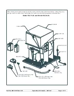
Page 21: ...ency gas type inside or outside mount and whether the heater is constructed of galvanized or stainless steel 1045 1305 Natural Gas 1045 0100 LP Propane Gas 1021 2501 0404 2742 3005 2130 3005 0102 Model SS 75 XL and Model SS 40 XL 3005 0108 6401 2890 1007 1614 6401 2881 1903 0100 120V 1018 1110 0404 2358 0408 1885 SS 40 XL only 1010 1317 LP Propane Gas 1010 2500 Natural Gas ...

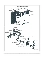
Page 22: ...6401 1140 0404 2739 1004 1406 0404 2740 1041 1488 1009 1500 1021 1500 1021 1496 1041 1491 1021 1495 3004 0100 LP Propane Gas 3004 0101 Natural Gas SEE MODEL NO 1004 1422 1004 1102 6401 1307 1004 7019 1005 0100 1001 1453 0408 4347 1901 0163 3002 5000 120V 1041 5004 Models SS 75 XL and SS 40 XL 3001 0111 ...

Page 23: ...ater Plate 1042 2693 3006 1581 0404 2348 3008 2257 3010 2139 1902 1137 3591 1851 3001 2862 6401 2881 0408 1883 1004 1388 0408 2314 SS 40 XL Only 1004 2881 0408 1231 1004 1388 1004 1412 6401 1726 1001 1452 0408 5017 3001 1740 0408 1146 3017 1302 120V 60 Hz Models SS 75 XL and SS 40 XL ...

Page 24: ...Part No 4801 1015 Rev 6 09 Super Saver XL Heater 120 Volt Page 24 of 25 NOTES ...

Page 25: ......

Reviews: