Part No. 4801-1015 Rev 6-09
Super-Saver XL Heater – 120 Volt
Page
12
of
25
9.2
1018 Series Hot Surface Ignition
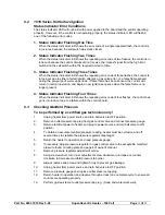
Status Indicator Error Conditions
The status indicator LED will not be lit with power applied to the board and the control operating
properly. However, if the control is not operating properly, the status indicator LED will flash in
one of the following error codes.
1. Status Indicator Flashing One Time
When the status indicator LED shows the error code of a single repeated flash, the control is
in lock-out, because the sail switch was stuck closed.
2. Status Indicator Flashing Two Times
When the status indicator LED shows the repeating error code of two flashes, the control is in
lock-out because the control circuits did not receive the “closed” signal from the high limit
switch and the sail switch within the required amount of time.
3. Status Indicator Flashing Three Times
When the status indicator LED shows the repeating error code of three flashes, the control is
in lock-out due to either a failed ignition attempt, a gas valve error, or a false flame sensed
during the pre-purge of warm-up periods. If false flame has been sensed, the control will
return to normal operation, and begin a new ignition sequence when the false flame is no
longer present.
4. Status Indicator Flashing Four Times
When the status indicator LED shows the repeating error code of four flashes, the control has
gone into lock-out due to a failure within the control board.
9.3 Checking
Manifold
Pressure
To be performed by a certified gas technician only!
1.
Unplug heater from power source and turn ball valve to OFF position.
2.
Remove outlet pressure tap plug from gas control valve and connect pressure gauge.
3.
Return electrical power to heater and plug to power source and turn ball valve to ON
position.
4.
To obtain an accurate manifold pressure reading, heater must be cycled on and off
several times to stabilize the pressure regulator diaphragm.
5.
Return the heater to operation and read pressure gauge.
6.
If necessary, adjust pressure regulator on gas control valve to the acceptable manifold
pressure found on rating plate and page 4 of owner’s manual.
7.
Remove pressure regulator adjustment screw.
8.
Using a screwdriver, turn inner adjustment screw clockwise to increase or counter
clockwise to decrease manifold pressure to burner.
9.
Always replace cap screw and tighten firmly to prevent gas leakage.
10.
Unplug heater from power source and turn ball valve to OFF position.
11.
Remove pressure gauge and replace outlet pressure tap plug.
12.
Return heater to operation and observe through at least one complete cycle to ensure all
controls are operating properly.
13.
Perform gas leak test at outlet pressure tap plug. (Soap and water work well).


