


File Management
24
3A6828B
File Management
Managing Pressure Test Results
Transferring Pressure Test Results
1. Insert a USB drive in the USB port (12) in the front
cover.
2. Press the Settings
button to display the Setup
screen.
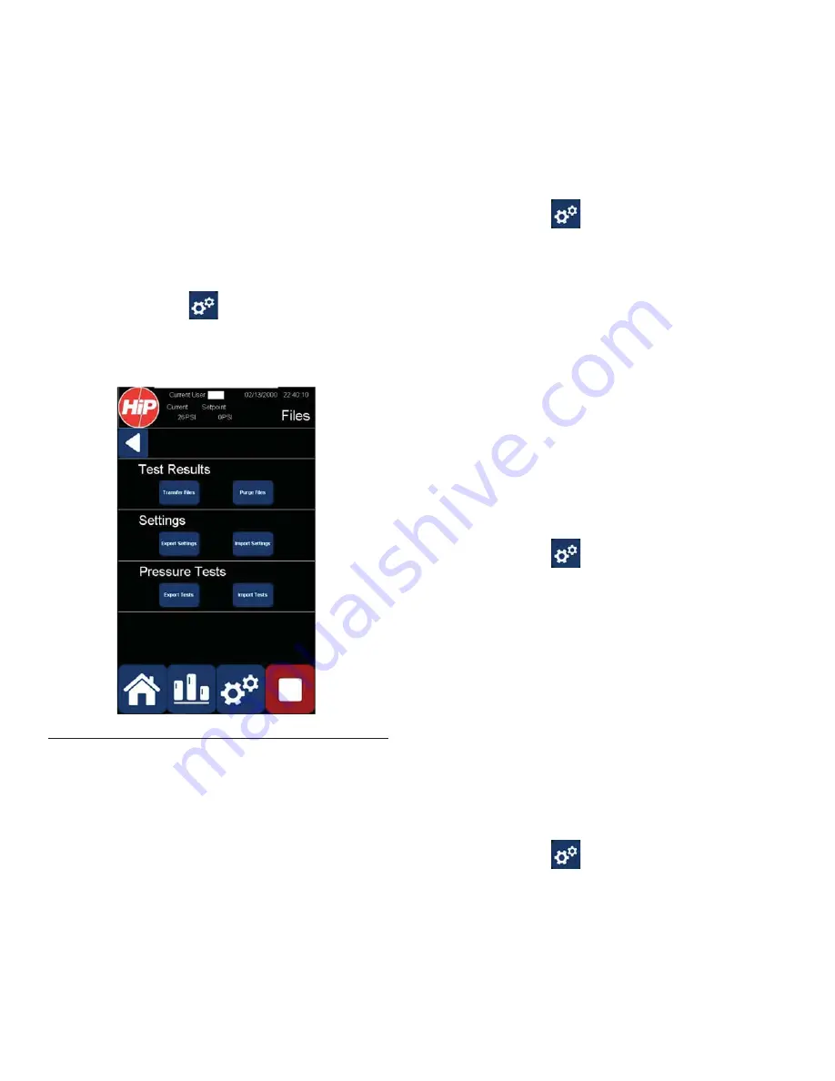
3. Select File Management to display the Files screen.
4. Press the Test Results-->Transfer Files button to
transfer all pressure test results to the USB drive.
5. Remove the USB drive from the USB port.
Purging Pressure Test Results
1. Press the Settings
button to display the Setup
screen.
2. Select File Management to display the Files screen.
3. Press the Test Results-->Purge Files button to
delete all pressure test results from the PT2020
controller.
Transferring System Settings
Exporting System Settings
This is useful for saving current settings when updating
the PT2020 software.
1. Insert a USB drive in the USB port (12) in the front
cover.
2. Press the Settings
button to display the Setup
screen.
3. Select File Management to display the Files screen.
4. Press the Settings-->Export Settings button to
transfer all system settings to the USB drive.
5. Remove the USB drive from the USB port.
Importing System Settings
This is useful for restoring saved settings after updating
the PT2020 software.
1. Insert a USB drive in the USB port (12) in the front
cover.
2. Press the Settings
button to display the Setup
screen.
3. Select File Management to display the Files screen.
4. Press the Settings-->Import Settings button to trans-
fer system settings from the USB drive.
5. Remove the USB drive from the USB port.
F
IG
. 26 Files Screen
Summary of Contents for 25D815
Page 32: ...Dimensions 32 3A6828B ...


