8
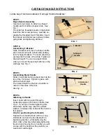
STEP 3.
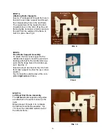
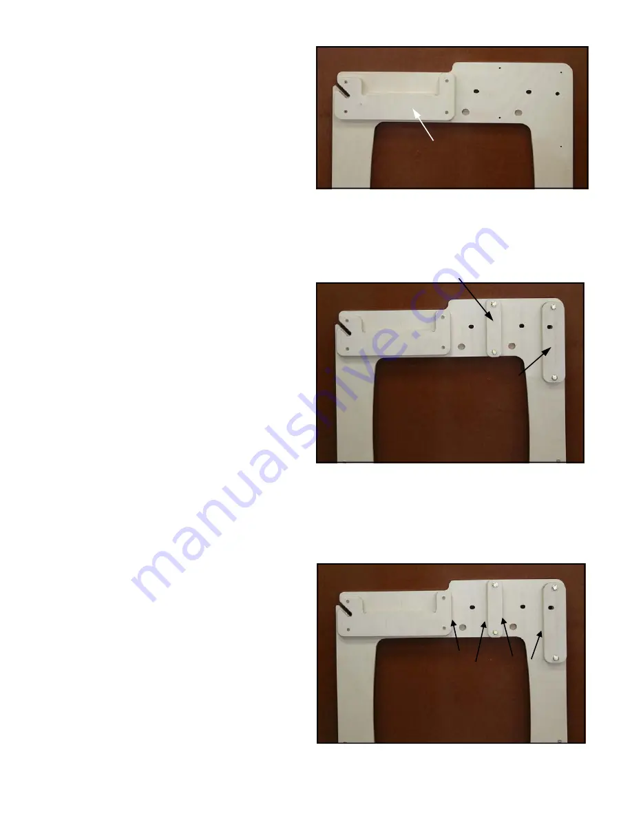
Template Support
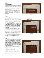
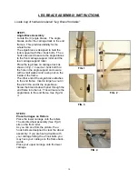
Locate the right end frame and the right tem-
plate support. Both inside and outside edges
of the end frames are rounded over. The
template supports are only rounded over on
one edge. The flat side goes against the end
frame for a close fit.
Lay the end frame on a flat surface and at-
tach the right-hand template board support
with four 1 1/4” Phillips head wood screws.
See Fig 3.
TEMPLATE SUPPORT
FIG. 3
STEP 4.
Roller Support Guide
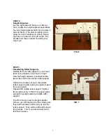
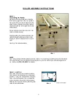
Locate the right front roller support guide and
the right middle roller support guide and lay
them on the right end frame as shown.
See
Fig. 4
. The purpose of the rectangular
guides is to keep the middle and rear roller
supports aligned vertically.
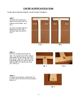
As with the template support, the side of the
guide without the rounded edge lies against
the end frame. The large hole in the front
support should line up with the hole in the
end frame.
You will be attaching the guides to the end
frame with (4) 1/4” x 1-1/4” hex head
screws. Place a 1/4” steel washer onto the
screw. Insert the hex head screw through
the guide, and then screw into the end frame
loosely. The screws will be tightened after
attaching the roller supports. There is a
wrench included in the “roller end hardware”
bag, that can be used for these screws.
STEP 5.
To Prevent Roller Supports From Sticking
In the ’End Frame Hardware bag’ you will
find blue strips of Teflon tape. These are ac-
tually clear strips of Teflon tape with blue
backing. Remove the blue backing and apply
the strips of tape to the wooden parts before
assembly.
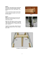
See Fig. 5
Apply 3 1/2" strip of Teflon tape to edge of
template support.
Apply 5" strip of Teflon tape to both edges of
middle roller support guide.
Apply 6" strip of Teflon tape to edge of front
roller support guide.
This tape will allow the wooden parts to
glide smoothly past each other when rais-
ing and lowering the roller supports.
FIG. 5
FRONT ROLLER
SUPPORT GUIDE
FRONT
OF
FRAME
REAR
OF
FRAME
FIG. 4
MIDDLE ROLLER
SUPPORT GUIDE
3 1/2”
5”
5”
6”


