3 Product Description
F3 DIO 16/8 01
Page 16 of 58
HI 800 177 E Rev. 1.01
For more information on how to configure line control in the user program, refer to the
HIMatrix Engineering Manual HI 800 101 E.
3.1.3
Safety-Related Digital Outputs
The state (HIGH, LOW) of each output is signaled by an individual LED. The following block
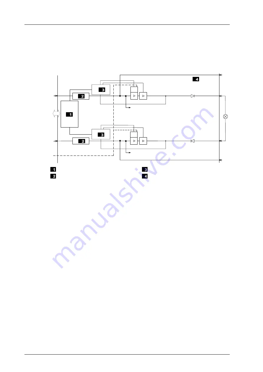
diagram shows how the two-pole digital outputs are connected:
DO1+
L
+
S
+
DO1
-
W
D
L
-
S
-
W
D
&
&
DOn-
DOn+
Connection to I/O BUs
Current Limiting
Logic
Two-Pole Output
Figure 5:
Block Diagram for Two-Pole Digital Outputs
The 1oo2 processor system directly energizes the digital outputs. Field zone and processor
zone are not galvanically isolated. The operating voltage directly supplies the outputs.
If a critical fauilure occurs, the processor system brings the outputs to the de-energized
state directly, via the I/O bus or indirectly, using the watchdog (second independent
shutdown function).
If communication is lost, the output is set to the initial value configured. This effect must be
taken into account for the behavior of the connected output.
If an overload occurs, one or all digital outputs are switched off. If the overload is removed,
the outputs are switched on again automatically, see Table 14.
3.1.3.1
Reaction in the Event of a Fault
If the device detects a faulty signal on a digital output, the affected module output is set to
the safe (de-energized) state using the safety switches.
If a fault in the device occurs, all digital outputs are switched off.
In both cases, the devices activates the
FAULT
LED.
The error code allows the user to configure additional fault reactions in the user program.


