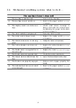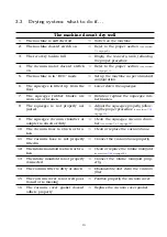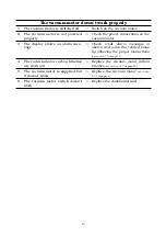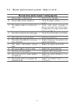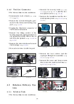
4.4.2
Traction Gearmotor
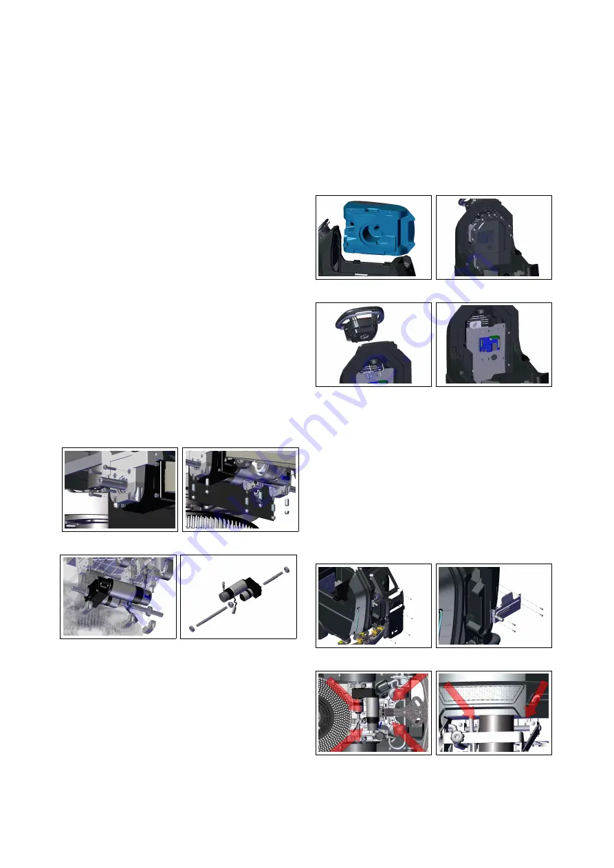
• Put the machine in safe conditions.
• Disassemble both wheels
(see section
at page
.
• Remove the 4 screws fixing the gear-
motor to the frame and bearing sup-
port
(see fig.
.
• Unplug the Electrical connector of
the Traction Gearmotor.
• Remove the fixing screws of the
bearing supports paying attention to
the gearmotor which will be free to
fall off to the ground
(see fig.
) (see
fig.
.
• Remove the drive shafts and remove
the bearings
(see fig.
.
• Proceed at reverse to refit the part.
4.4.2-33
4.4.2-34
4.4.2-35
4.4.2-36
4.5
Solution Delivery Sys-
tem
4.5.1
Solution Tank
• Put the machine in safe conditions.
• Remove the recovery tank
(see section
at page
) (see fig.
and the elec-
tric system carter
(see fig.
.
• Remove the handlebar and the elec-
trical system panel
(see fig.
) (see fig.
.
4.5.1-37
4.5.1-38
4.5.1-39
4.5.1-40
• Remove the rear carters and the
squeegee lifting lever assembly
(see fig.
) (see fig.
.
• Remove the lower and front screws
that secure the tank to the frame
(see
fig.
) (see fig.
.
4.5.1-41
4.5.1-42
4.5.1-43
4.5.1-44
26
Summary of Contents for TRIDENT T20SC PRO
Page 1: ...SERVICE MANUAL TRIDENT T20SC PRO Version AB Date November 7 2018 Document Number 10077483...
Page 4: ...Part I Product Introduction 4...
Page 8: ...Part II Anomalies Resolution Guide 8...
Page 28: ...Part III Machine Description 28...

