background image

Before powering-up the case, be certain that all of the steps listed below 

have been completed to ensure proper case functionality, safety and compli-

ance with warranty terms.


Have you thoroughly examined the case for shipping damage? (see    


pg. 2)


Have you removed and discarded the casters? (see pg. 3)


Have you checked the vertical plumb of the case?  The horizontal 


level? (see pg. 3)


Have you applied the foam tape gasket and sealant between adjoining   


cases? (see pg. 3)


Have you sealed the case-to-case joints by applying caulk and acrylic   


tape to the pipe-chase seam? (see pg. 4)


Have you removed the shipping blocks from the refrigeration lines?    


(see pg. 5)


Have you sealed any tank penetrations? (see pg. 5)


Have you cleared the case of any loose packaging or case materials?    


(see pg. 6)

PRE-POWER CHECKLIST

ATTENTION!

Be certain to clear the case of any loose 

packaging or case materials before ener-

gizing the case.  Failure to do so may re-

sult in case damage or malfunction.

6

Summary of Contents for 3NDML-NRG

Page 1: ...have experience working with commercial refrigerated display merchandisers and storage cabinets For a list of Hillphoenix authorized installation service contractors please visit our Web site at www hillphoenix com 3NDML NRG General Information 2 Case Installation 3 4 Case Connections 5 Pre Power Checklist 6 Lighting and Power Supplies 7 Airflow Defrost Temperature Control 8 Fans Case Maintenance ...

Page 2: ...tted in any form or by any means i e electronic or mechanical including photocopying recording or any other information storage and retrieval system without express written permission from Hillphoenix VERSION 1 07 13 New manual format V1 01 07 13 Updated Electrical Data Appendix A REVISION HISTORY ii ...

Page 3: ...www hillphoenix com PRECAUTIONARY NOTICES At Hillphoenix the safety of our customers and employ ees as well as the ongoing performance of our products are top priorities To that end we call out important mes sages in all Hillphoenix installation and operations hand books with an accompanying alert symbol All of these notices are meant to provide information about potential dangers to personal heal...

Page 4: ... 1109 CASE DAMAGE Claims for obvious damage must be 1 noted on either the freight bill or the express receipt and 2 signed by the car rier s agent otherwise the carrier may refuse the claim If damage becomes apparent after the equipment is unpacked retain all packing materials and submit a written request to the carrier for inspection within 14 days of receipt of the equipment LOST MISSING ITEMS E...

Page 5: ...case joint The grill lifts out without fasteners and may be easily removed to gain clear access to the case to case joining bolts 3 Follow the single case installation instructions for the first case then position the next case in the line up ap proximately 3 away Remove the casters on the end that is closest to the first case 4 Apply the foam tape gasket supplied and a bead of butyl or silicone s...

Page 6: ...cluded see Appendix D for detailed installation instructions CASE INSTALLATION 2 Re install shelves Be aware that differing shelf con figurations will affect energy consumption and case performance 3 Tighten all cornice joints as needed Fig 4 Working outward from the center of the line up loosen the fas teners on the top and slide the cornices in one direction so that each joint aligns tightly tog...

Page 7: ...PVC material and is located in the front center of the case for convenient access The P trap furnished with the case is construct ed of schedule 40 PVC pipe Fig 6 Care should be given to ensure that all connections are water tight and sealed with the appropriate PVC or ABS cement The drain lines can be run left or right of the tee with the proper pitch to satisfy local drainage requirements Since ...

Page 8: ...ve you applied the foam tape gasket and sealant between adjoining cases see pg 3 Have you sealed the case to case joints by applying caulk and acrylic tape to the pipe chase seam see pg 4 Have you removed the shipping blocks from the refrigeration lines see pg 5 Have you sealed any tank penetrations see pg 5 Have you cleared the case of any loose packaging or case materials see pg 6 PRE POWER CHEC...

Page 9: ...m Doing so will damage the LED system and increases the chance of safety issues injury CAUTION Using improper DC power supplies may damage the luminaires resulting in sub standard operation and increased chanc es of safety issues injury DANGER SHOCK HAZARD Always disconnect power to case when servicing or cleaning Failure to do so may result in serious injury or death Fig 12 Clear view of the powe...

Page 10: ... defrost termination sensor will be mounted to the dump line the sensor should always be mounted on the coil side of the check valve or solenoid valve Finally if timed off defrost is used the refrigeration cycle is simply turned off by the case con trols for a specified amount of time therefore there are generally no active defrost components utilized The discharge air probe monitors the temperatu...

Page 11: ...e turned off long enough to clean any frost or ice from coil and pans Remove kickplate and clean underneath the case with a broom and a long handled mop Use warm water and a disinfecting cleaning solution when cleaning un derneath the cases Fig 16 Single piece fan plenum and coil cover SINGLE PIECE FAN PLENUM SWINGS UP FOR EASY CLEANING FAN PLENUM COIL FANS CASE MAINTENANCE FANS The evaporator fan...

Page 12: ...A1 A2 3NDML NRG ELECTRICAL DATA CASE DIMENSIONS B1 B2 ELECTRICAL WIRING C1 SPORLAN PRESSURE TEMPERATURE CHART D1 D5 SEISMIC BRACKET INSTALLATION APPENDIX 11 ...

Page 13: ...oduce 1177 1232 6 8 28 34 350 Produce Beverage 1059 1091 6 8 32 37 350 1 NOTE indicates that feature is not an option on this case model 2 BTUH ft notes Listed BTUH ft indicate unlighted shelves For LED lighting add 36 BTUH per 4 lighted shelf and 27 BTUH per 3 lighted shelf to determine Total Lighting BTUH Load then divide the Total Lighting BTUH Load by the length of the case For T8 lighted shel...

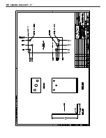
Page 14: ...VC DRAIN CONNECTION KICK PLATE LOCATION 4 CASE ONLY 62 in 157 5 cm 14 3 4 in 37 5 cm 40 1 4 in 102 3 cm Dh 25 5 8 in 65 1 cm 9 3 8 in 23 9 cm 35 7 8 in 91 0 cm 24 1 4 in 61 5 cm 33 5 8 in 85 4 cm LOAD LIMIT LINE 4 1 8 in 10 5 cm COIL PLENUM CLASSIC 2 STANDARD FRONT L C 72 in 182 9 cm 6 CASE 44 1 2 in 112 9 cm BASE FRAME ELECTRICAL JUNCTION BOX WIRING PER LOCAL CODES REFRIGERATION 31 in 78 8 cm 23 ...

Page 15: ... CONTAINED SERVICE LIGHT HI PRESSURE HIGH PRESSURE SWITCH DUAL PRESSURE SWITCH CONDENSING UNIT POWER CONDENSING UNIT FAN 1 2 L1 L3 L2 13 14 16 15 18 17 10 9 36 37 4 3 40 5 6 7 8 12 11 60 62 19 20 22 21 23 28 27 29 31 30 39 38 41 42 24 25 34 35 33 32 N 58 57 53 54 49 50 51 52 47 48 45 46 44 220V IG RECEPTACLE GFI RECEPTACLE HUMIDIFIER 26 43 56 55 70 71 GREEN REFRIGERATED PAN SOLENOID REFRIGERATED P...

Page 16: ...BLUE WHITE BLACK 3NDML WIRING DIAGRAM B2 ...

Page 17: ...4 388 0 18 7 8 17 0 52 7 55 6 31 4 394 3 19 7 2 17 7 54 0 56 9 32 4 400 7 20 6 7 18 4 55 3 58 3 33 5 407 2 21 6 1 19 1 56 6 59 6 34 6 413 8 22 5 6 19 9 58 0 61 0 35 7 420 4 23 5 0 20 6 59 3 62 4 36 8 427 1 24 4 4 21 3 60 7 63 8 37 9 433 8 25 3 9 22 1 62 1 65 3 39 0 440 7 26 3 3 22 9 63 5 66 7 40 2 447 6 27 2 8 23 7 64 9 68 2 41 4 454 6 28 2 2 24 5 66 4 69 7 42 6 461 7 29 1 7 25 3 67 8 71 2 43 8 46...

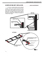
Page 18: ...lable for all base frame heights CONSTRAINT BRACKET ATTACH TO TOP OF CASE USE 3 10 SELF TAPPING SCREWS ATTACK BRACKET TO WALL USE 1 0 5 OR 2 0 375 ANCHORS BASE FRAME CONSTRAINT BRACKET 2 PER CASE BRACKET SHOWN HERE IS FOR A 5 TALL BASE FRAME CONSTRAINT BRACKETS ARE ALSO AVAILABLE FOR ALL BASE FRAME HEIGHTS USE 3 10 SELF DRILLING SELF TAPPING SCREWS FOR ATTACHMENT TO THE BASE FRAME ALTERNATE LOCATI...

Page 19: ...SEISMIC BRACKET 5 D2 ...

Page 20: ...SEISMIC BRACKET 7 D3 ...

Page 21: ...SEISMIC BRACKET 11 D4 ...

Page 22: ...SEISMIC BRACKET 15 D5 ...

Page 23: ... sales tax or upgrading 5 When the operation is impaired due to improper installation 6 When installation and startup forms are not properly complete or returned within two weeks after startup THIS PLAN DOES NOT COVER CONSEQUENTIAL DAMAGES Manufacturer shall not be liable under any circumstances for any consequential damages including loss of profit additional labor cost loss of refrigerant or foo...

Page 24: ...olution or water directly on fan motors or any electrical connections All lighting components must be dried thoroughly before installation and before re energizing the lighting circuit Please refer to the Case Maintenance section of this installation manual BDM0915 1925 Ruffin Mill Road Colonial Heights VA 23834 Due to our commitment to continuous improvement all specifications are subject to chan...

Reviews:

Related manuals for 3NDML-NRG