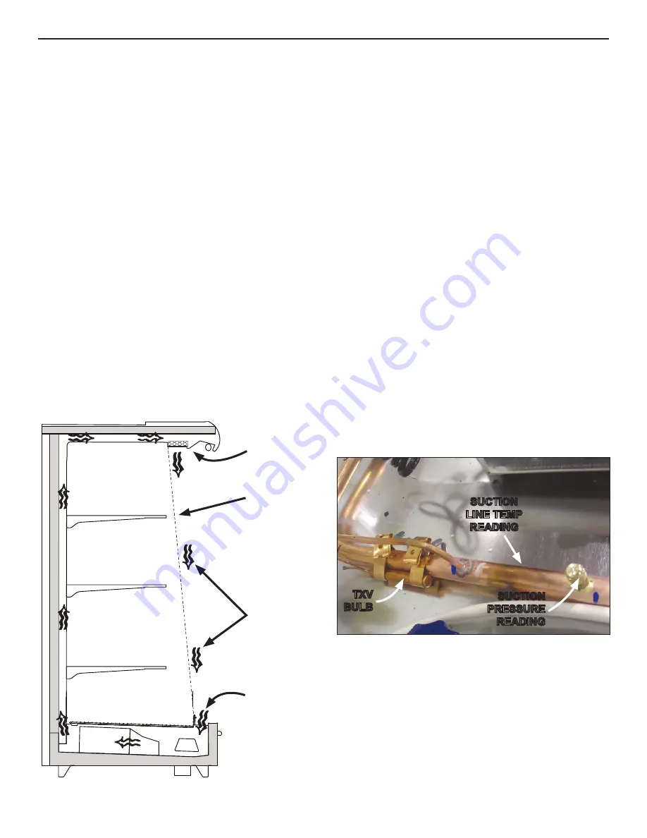
Fig. 13 Airflow
RETURN
AIR
DISCHARGE
AIR
LOAD
LIMIT
Fig. 14 Obtain pressure and temperature readings
SUCTION
LINE TEMP
READING
TXV
BULB
SUCTION
PRESSURE
READING
AIR FLOW & PRODUCT LOAD
It is important that you do not overload the food product dis-
play so that it impinges on the air flow pattern - overloading
will cause malfunction and the loss of proper temperature
levels, particularly when discharge and return air sections
are covered. Please keep products within the load limit line
shown on the diagram below (Fig. 13).
DEFROST & TEMPERATURE CONTROLS
Hillphoenix cases utilize electric, hot gas, or timed-off
defrost. The primary components used for the defrost
cycle are the various defrost termination sensors, which
work to terminate the defrost cycle in the case. These
controls may include 1) a Klixon
®
thermostat, 2) a sensor
probe, or 3) a dial-type thermostat with sensor bulb (the
thermostat will always be mounted with the electrical con-
trols of the case - i.e., in the electrical junction box, in the
electrical raceway, etc.).
If electric defrost is used, the defrost termination sensor
will be located either behind the rear baffle or mounted to
the coil. If hot gas defrost is used, the defrost termination
sensor will be mounted to the dump line - the sensor
should always be mounted on the coil-side of the check
valve or solenoid valve. Finally, if timed-off defrost is used,
the refrigeration cycle is simply turned off by the case con-
trols for a specified amount of time; therefore, there are
generally no active defrost components utilized.
The discharge air probe monitors the temperature of the
discharge air and may be used as the defrost termination
sensor. The probe can generally be found behind the rear
baffle, in the upper baffle, or in front of the honeycomb.
NOTE: if the discharge air probe is used for defrost
termination, none of the termination sensors listed
earlier will be installed in the case.
For more detailed information on suggested defrost times
and settings, see
Appendix A
. Further adjustments may
be required depending on store conditions.
DETERMINING SUPERHEAT
To identify proper superheat settings, complete the follow-
ing:
1. Obtain suction pressure from access port; obtain suc-
tion line temperature from area near TXV bulb at the
outlet of evaporator coil (Fig. 14).
2. Using the suction pressure reading, convert pressure
to temperature using temperature pressure chart (
see
Appendix C
).
3. Finally, subtract the converted temperature reading
from the actual temperature reading for superheat set-
ting.
AIRFLOW, DEFROST & TEMPERATURE CONTROLS
AIR FLOW
8
Summary of Contents for 3NDML-NRG
Page 16: ...BLUE WHITE BLACK 3NDML WIRING DIAGRAM B2 ...
Page 19: ...SEISMIC BRACKET 5 D2 ...
Page 20: ...SEISMIC BRACKET 7 D3 ...
Page 21: ...SEISMIC BRACKET 11 D4 ...
Page 22: ...SEISMIC BRACKET 15 D5 ...


